Communication terminal

a technology of communication terminals and terminals, applied in the field of communication terminals, can solve the problems of inability to secure the expansion space of the housing of a small-sized communication terminal, the inability to avoid disposing the coils for close-proximity communication and power transmission near each other, and the inability to avoid disposing the coils for close-proximity communication and the coil for power transmission. to achieve the effect of stable electrical characteristics

Active Publication Date: 2015-03-19
MURATA MFG CO LTD
View PDF1 Cites 68 Cited by
  • Summary
  • Abstract
  • Description
  • Claims
  • Application Information

AI Technical Summary

Benefits of technology

[0027]According to various preferred embodiments of the present invention, stable elect...

Problems solved by technology

Extensive space cannot be secured within the housing of a small-sized communication terminal, and as a result, it is impossible to avoid disposing a coil for close-proximity communication and a coil for power transmission near each other.
There is thus a risk that the coil for close-proximity communication and the coil for power transm...

Method used


Image

  • Communication terminal
  • Communication terminal
  • Communication terminal

Examples


first preferred embodiment

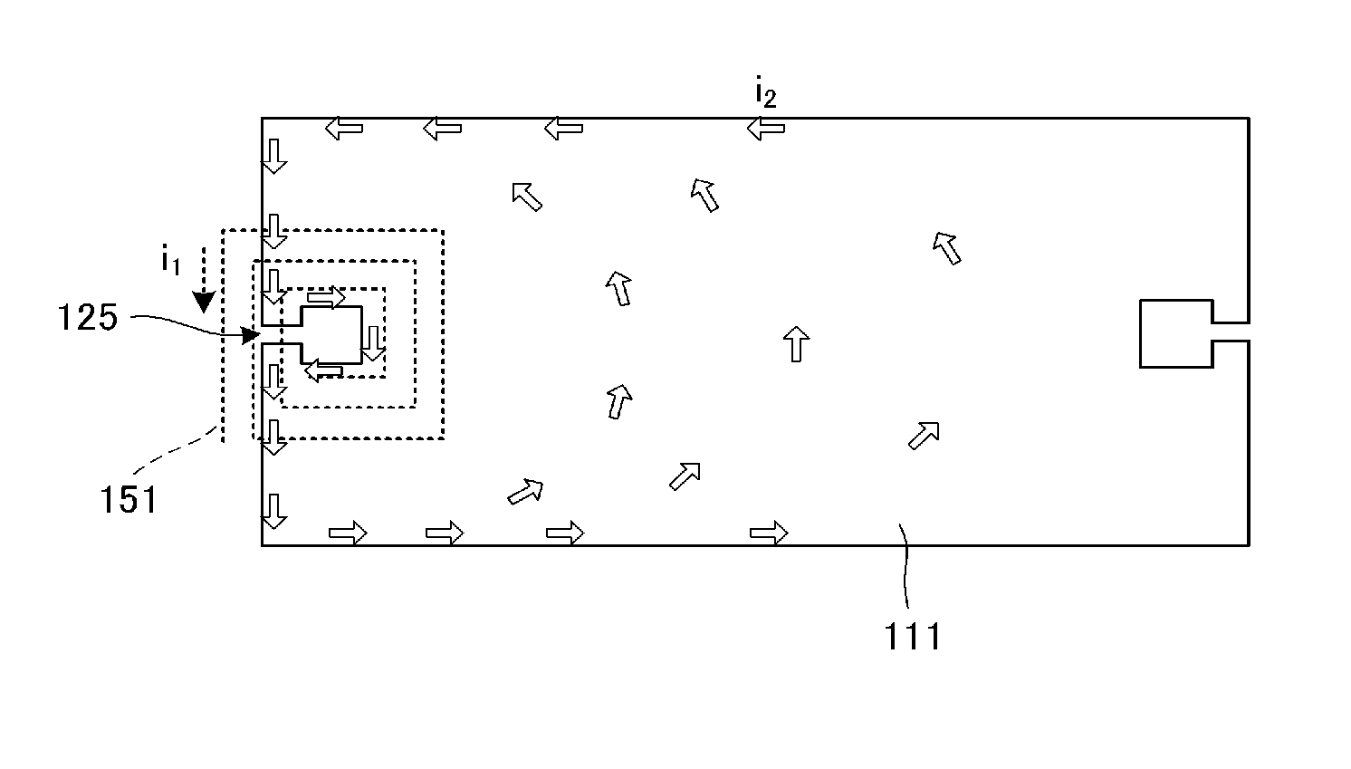
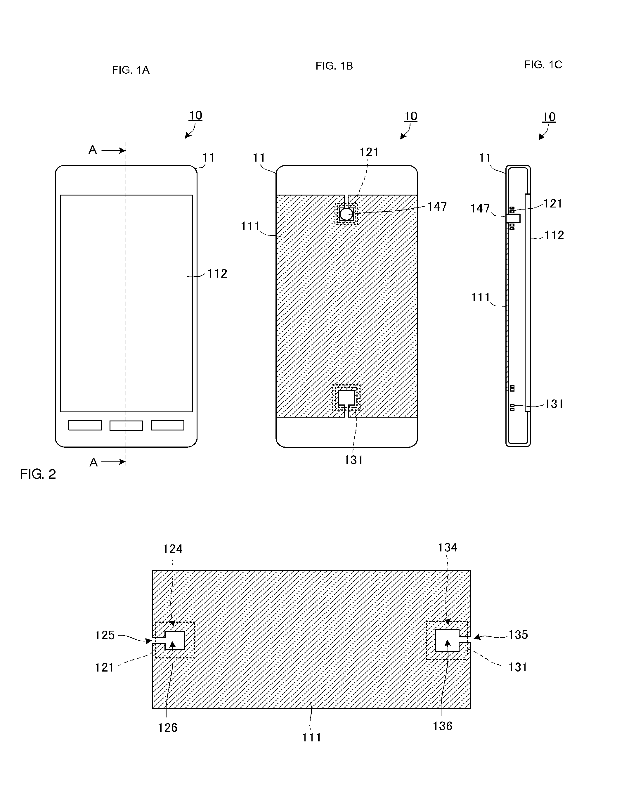
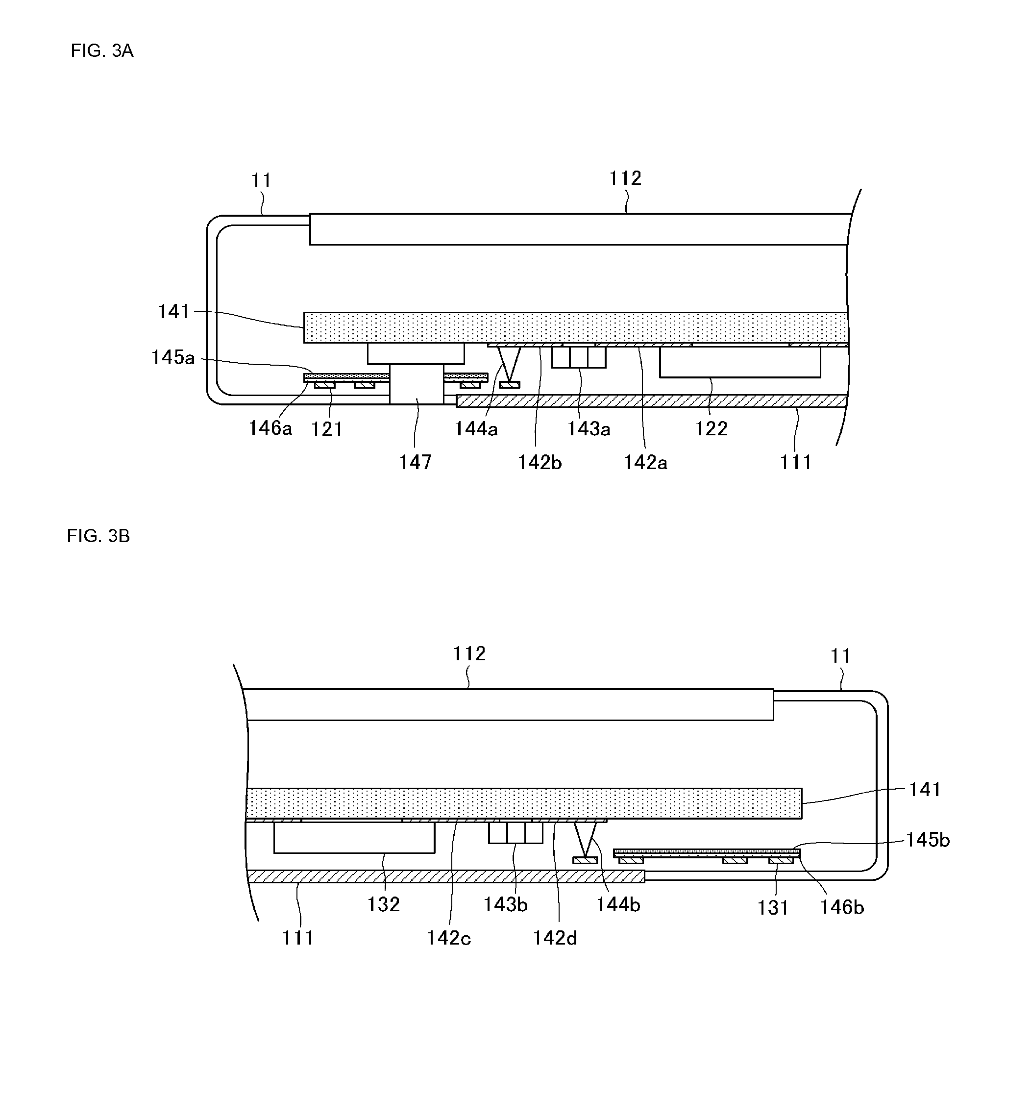
[0039]A communication terminal according to a first preferred embodiment of the present invention will be described hereinafter. The communication terminal according to the present preferred embodiment preferably is a smartphone. However, the communication terminal may be a music player, a laptop PC, a tablet terminal, or the like provided with a communication function, for example. FIG. 1A is a plan view illustrating a front surface side of a communication terminal 10 according to a first preferred embodiment of the present invention. FIG. 1B is a plan view illustrating a rear surface side of the communication terminal 10. FIG. 1C is an A-A cross-sectional view illustrating the communication terminal 10. FIG. 2 is a plan view illustrating a positional relationship among a metal plate 111, a close-proximity communication coil 121, and a power transmission coil 131. However, note that FIG. 2 illustrates the number of turns in and the dimensions of each coil so that the positional rel...

second preferred embodiment

[0075]A communication terminal 20 according to a second preferred embodiment of the present invention will be described hereinafter. FIG. 8A is a plan view illustrating a rear surface side of the communication terminal 20. FIG. 8B is a B-B cross-sectional view illustrating the communication terminal 20. FIG. 8C is a diagram illustrating a power transmission module in the communication terminal 20, showing primary components in an enlarged manner along the B-B cross-section.

[0076]A loop portion 231 is provided in the metal plate 111 preferably by forming a slit having the same shape as the slit portion 135 according to the first preferred embodiment in the metal plate 111. The loop portion 231 configures a power transmission coil.

[0077]The communication terminal 20 does not include the power transmission coil 131, the magnetic sheet 145b, or the flexible board 146b according to the first preferred embodiment. Meanwhile, the pin terminal 144b is connected to the metal plate 111.

[0078]...


PUM


Abstract

A communication terminal includes a close-proximity communication coil, a power transmission coil, and a metal plate. The close-proximity communication coil is configured to be used in a close-proximity communication system. The power transmission coil is configured to be used in a contactless power transmission system. At least a portion of the metal plate is disposed between the close-proximity communication coil and the power transmission coil. The close-proximity communication coil and the power transmission coil are disposed in non-overlapping locations when viewed from a direction perpendicular or substantially perpendicular to a main surface of the metal plate. At least one of the close-proximity communication coil and the power transmission coil electromagnetically couples with the metal plate.

Description

BACKGROUND OF THE INVENTION[0001]1. Field of the Invention[0002]The present invention relates to communication terminals provided with close-proximity communication systems and contactless power transmission systems.[0003]2. Description of the Related Art[0004]NFC (Near-Field Communication), RFID (Radio Frequency Identification), and such systems are examples of close-proximity communication systems. The RFID system is a close-proximity communication system that uses magnetic coupling between a R / W-side coil and a tag-side coil, and is used for monetary transactions, authentication, and the like.[0005]Qi (registered trademark), meanwhile, is a power transmission system that uses magnetic coupling, serving as an example of a contactless power transmission system. This power transmission system can transmit power without contact, using magnetic coupling between a power transmitting apparatus-side coil and a communication terminal-side coil.[0006]Japanese Unexamined Patent Application ...

Claims


Application Information

Patent Timeline
IPC IPC(8): H01F27/36H01F27/28H04W4/00H02J5/00H01Q1/52H01Q7/06H04B5/02H04M1/02H04W4/80
CPCH01F27/36H04W4/008H01F27/28H02J5/005H04M1/0202H01Q1/243H01Q1/248H01Q7/00H01Q21/28H02J7/0042H04B5/0031H04B5/0037H04B5/0081H04B5/0087H01F38/14H04W4/80H02J50/10H01F27/363H04M1/02H02J50/90H02J50/12
Inventor KATO, NOBORUOZAWA, MASAHIRO
Owner MURATA MFG CO LTD
Why Eureka
Try Eureka