Rotary machine with direct drive

a rotary machine and direct drive technology, applied in mechanical energy handling, cooling/ventilation arrangement, transportation and packaging, etc., can solve the problems of difficult to meet the high demands on precision, difficult to lubricate the bearings in which the carousel is guided, and difficult to lubricate the toothings, etc., to achieve low wear at the bearing, not very susceptible to failure, and high liquid thermal capacity

Inactive Publication Date: 2015-03-19
KRONES AG
View PDF6 Cites 6 Cited by
  • Summary
  • Abstract
  • Description
  • Claims
  • Application Information

AI Technical Summary

Benefits of technology

[0007]The rotary machine according to the invention is characterized in that the rotating part and the stationary part are embodied such that they together form the drive of the machine, the rotating part forming the rotor and the stationary part forming the stator of an electric motor. With this direct drive, a drive of the rotating part of the container treatment machine or rotary machine may be accomplished in a technically simple manner, and a high-maintenance transmission can be eliminated. Furthermore, rotation may be adjusted much more precisely thus clearly improving the achieved treatment results.
[0020]The cooling medium might be a gas or a liquid. While gas cooling is inexpensive and not very susceptible to failures, liquid cooling has the advantage that, due to the high thermal capacity of the liquid and the better heat exchange, more effective cooling may be realized.

Problems solved by technology

However, since in many cases very complicated transmission systems are used and for a carousel, even multiple servomotors for the drive are sometimes provided, malpositions may occur in particular due to a gear backlash.
This makes it difficult to meet the high demands on precision, in particular during the labeling and printing of containers.
Furthermore, the lubrication of the bearings in which the carousel is guided and of the toothings is very complicated, and a large installation space for accommodating the complete drive system is required.

Method used


Image

  • Rotary machine with direct drive
  • Rotary machine with direct drive
  • Rotary machine with direct drive

Examples


Embodiment Construction

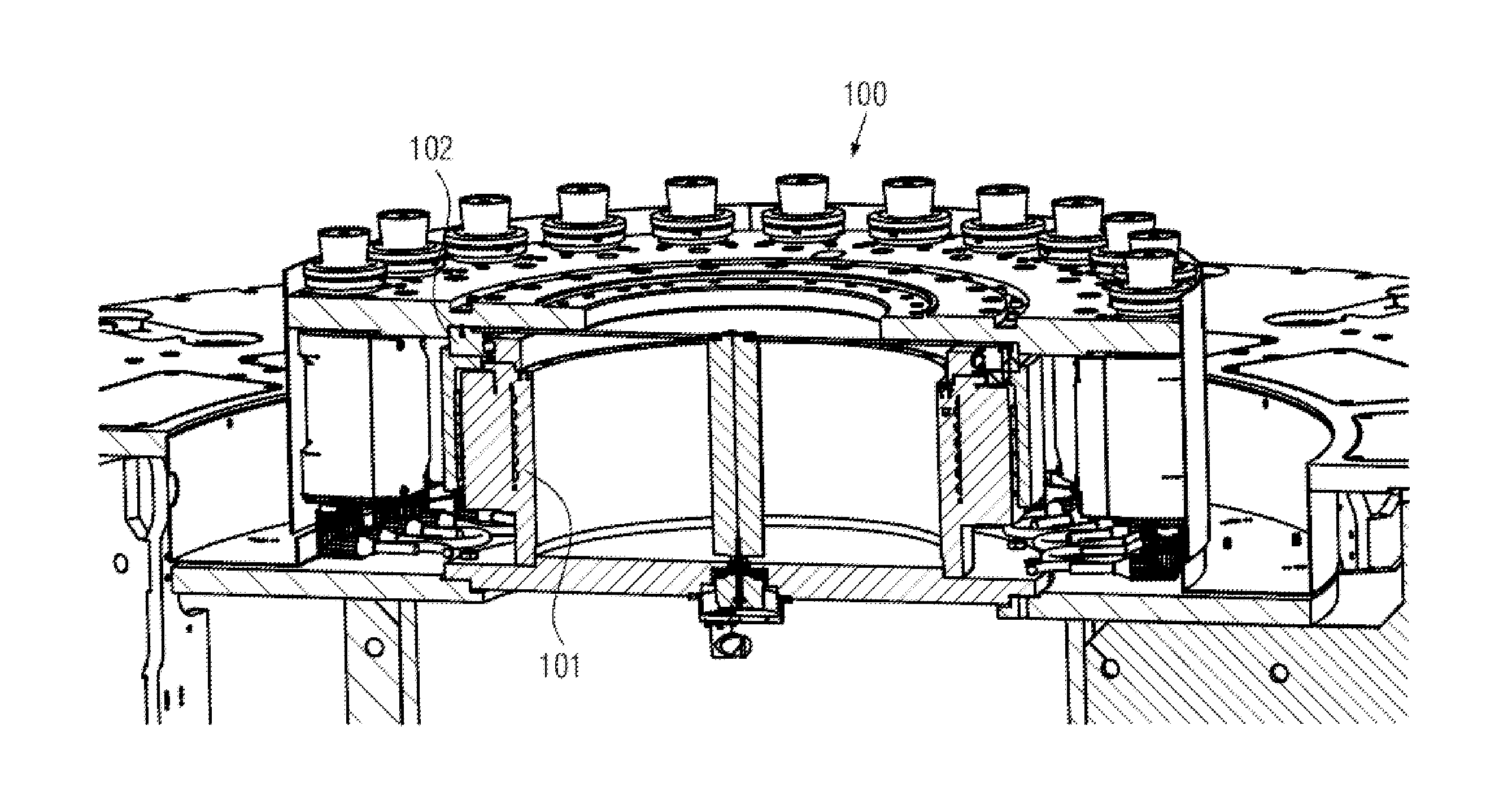
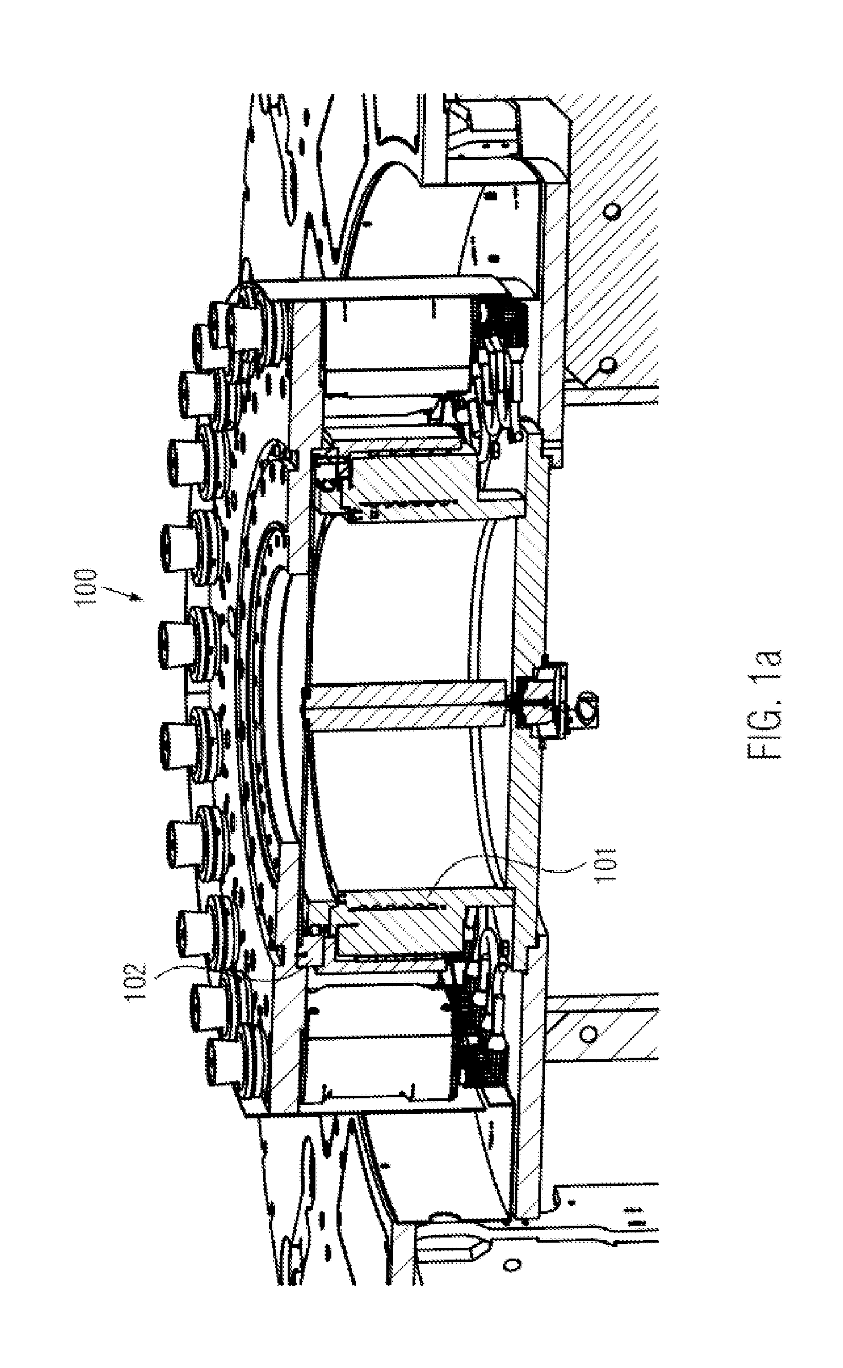
[0029]FIG. 1a shows a rotary machine 100 according to the invention. It comprises a stationary part 101 and a rotating part 102. Typically, container treatment stations or container clamping stations or elements for fixing the containers or container transport elements are arranged on the rotating part 102. Depending on the embodiment of the rotary machine 100, these may strongly differ. By way of example, the rotating part in a direct printing machine comprises several container treatment stations or container clamping stations. The latter may comprise, for example, individual rotary plates and printing modules associated with them. At the stationary part 101 of the rotary machine, further components may be arranged, for example, ink storage tanks, labeling or printing units, or the like, depending on the design of the rotary machine. Here, most diverse embodiments are already known which may depend on the type of the container treatment machine.

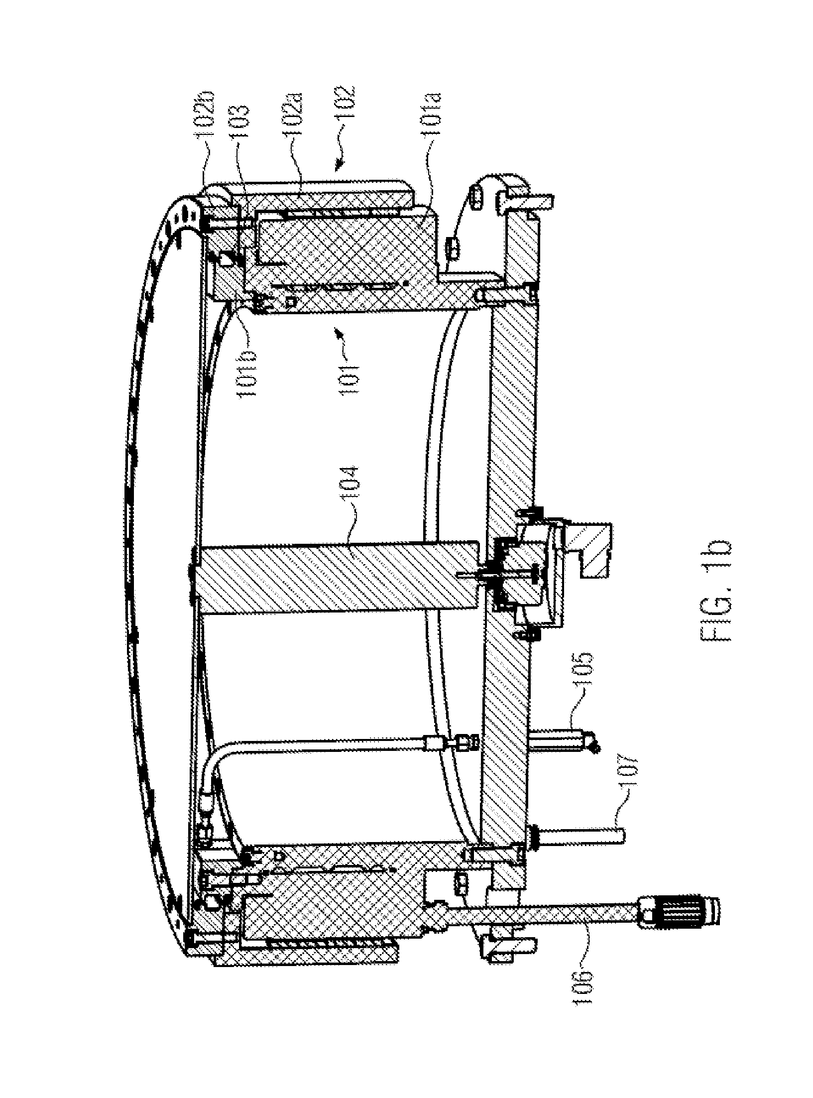
[0030]Basically, the stationary part...


PUM

PropertyMeasurementUnit
poweraaaaaaaaaa
areaaaaaaaaaaa
speedaaaaaaaaaa

Abstract

Rotary machine, in particular container treatment machine, including a rotating part which has several treatment stations, and a stationary part, the rotating part and the stationary part are embodied such that they together form the drive of the machine, the rotating part forming the rotor and the stationary part forming the stator of an electric motor.

Description

CROSS-REFERENCE TO RELATED APPLICATION[0001]The present application claims priority to German Application No. 102013218438.7, filed Sep. 13, 2013. The priority application, DE 102013218438.7, is hereby incorporated by reference.[0002]FIELD OF THE DISCLOSURE[0003]The present invention relates to a rotary machine, in particular the drive of a rotary machine.[0004]PRIOR ART[0005]Rotary machines, for example those in the beverages processing industry, are well-known. For example, there are stretch-blow molding machines or labeling machines as well as direct printing machines for treating containers which are embodied as rotary machines and thus may operate continuously and / or discontinuously. The connection between the rotary or the rotating part of said rotary machines is often realized via ball bearing slewing rims. The latter comprise toothings, so that a connection to a servomotor, which will then drive the corresponding carousel, may be established, for example via a pinion. Howeve...

Claims


Application Information

Patent Timeline
Patent Type & Authority Applications(United States)
IPC IPC(8): H02K7/14H02K9/08H02K11/00H02K7/08H02K3/04
CPCH02K7/14H02K7/08H02K9/08H02K11/0015H02K3/04B67B1/08B29C49/36H02K26/00H02K11/21H02K7/1016B65G23/00
Inventor SCHROLL, BERNDLAUMER, ROLANDHUMELE, HEINZSTOIBER, CHRISTIANKRAUS, ANDREASPEUTL, AUGUST
Owner KRONES AG
Why Eureka
Try Eureka