Imaging lens and imaging apparatus equipped with the imaging lens

a technology of imaging lens and imaging apparatus, which is applied in the field of fixed focus imaging lens, can solve the problems of difficult application of this imaging lens to an imaging element, excessive inability to obtain a sufficient maximum image height with respect to the total length of the lens, etc., to achieve short total length, reduce production costs, and wide angle of view

Active Publication Date: 2015-03-19
JIANGXI OFILM OPTICAL CO LTD
View PDF3 Cites 14 Cited by
  • Summary
  • Abstract
  • Description
  • Claims
  • Application Information

AI Technical Summary

Benefits of technology

[0039]According to the first and second imaging, lenses of the present invention, the configuration of each lens element is optimized within a lens configuration having five lenses as a whole, and all of the lenses are single lenses. Therefore, adhesive attachment steps become unnecessary in the production steps of the imaging lenses, thereby suppressing production costs, and lens systems that can achieve a wide angle of view and a short total length, which has a large image size and high imaging performance from a central angle of view to peripheral angles of view, can be realized.
[0040]The imaging apparatus of the present invention outputs image signals corresponding to optical images formed by the first or second imaging lens of the present invention. Therefore, the imaging apparatus of the present invention is capable of obtaining high resolution photographed images.

Problems solved by technology

However, the imaging lens disclosed in U.S. Patent Application Publication No. 20110181963 cannot obtain a sufficient maximum image height with respect to the total length of the lens.
Therefore, it is difficult for this imaging lens to be applied to an imaging element having a comparatively large image size that satisfies the demand for an increased number of pixels.
In the case that the entirety of the imaging lens disclosed in U.S. Patent Application Publication No. 20110181963 is proportionately enlarged to meet a desired image size, the total length of the lens will become excessively long, and shortening of the total length of the lens cannot be realized.
For this reason, the imaging lenses disclosed in U.S. Pat. No. 7,274,515 and Korean Patent Publication No. 10-2009-0055115 that satisfy the above power configuration incur cost for adhesive agents for adhesively attaching the cemented lenses together, and also involve adhesive attachment steps in addition to conventional production steps.
Therefore, it is difficult for these imaging lenses to be produced at low cost.

Method used


Image

  • Imaging lens and imaging apparatus equipped with the imaging lens
  • Imaging lens and imaging apparatus equipped with the imaging lens
  • Imaging lens and imaging apparatus equipped with the imaging lens

Examples


Embodiment Construction

[0061]Hereinafter, embodiments of the present invention will be described in detail with reference to the attached drawings.

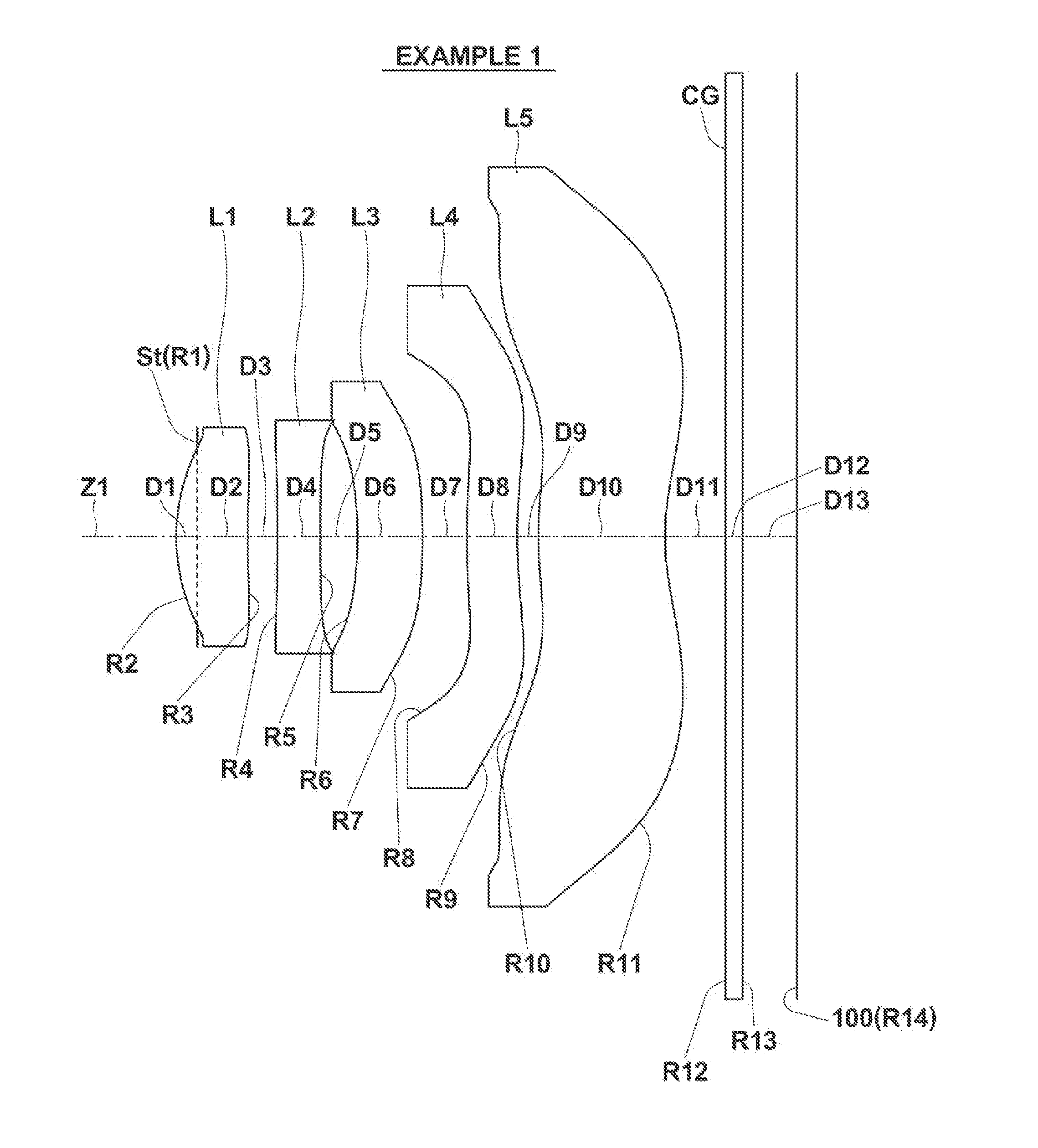
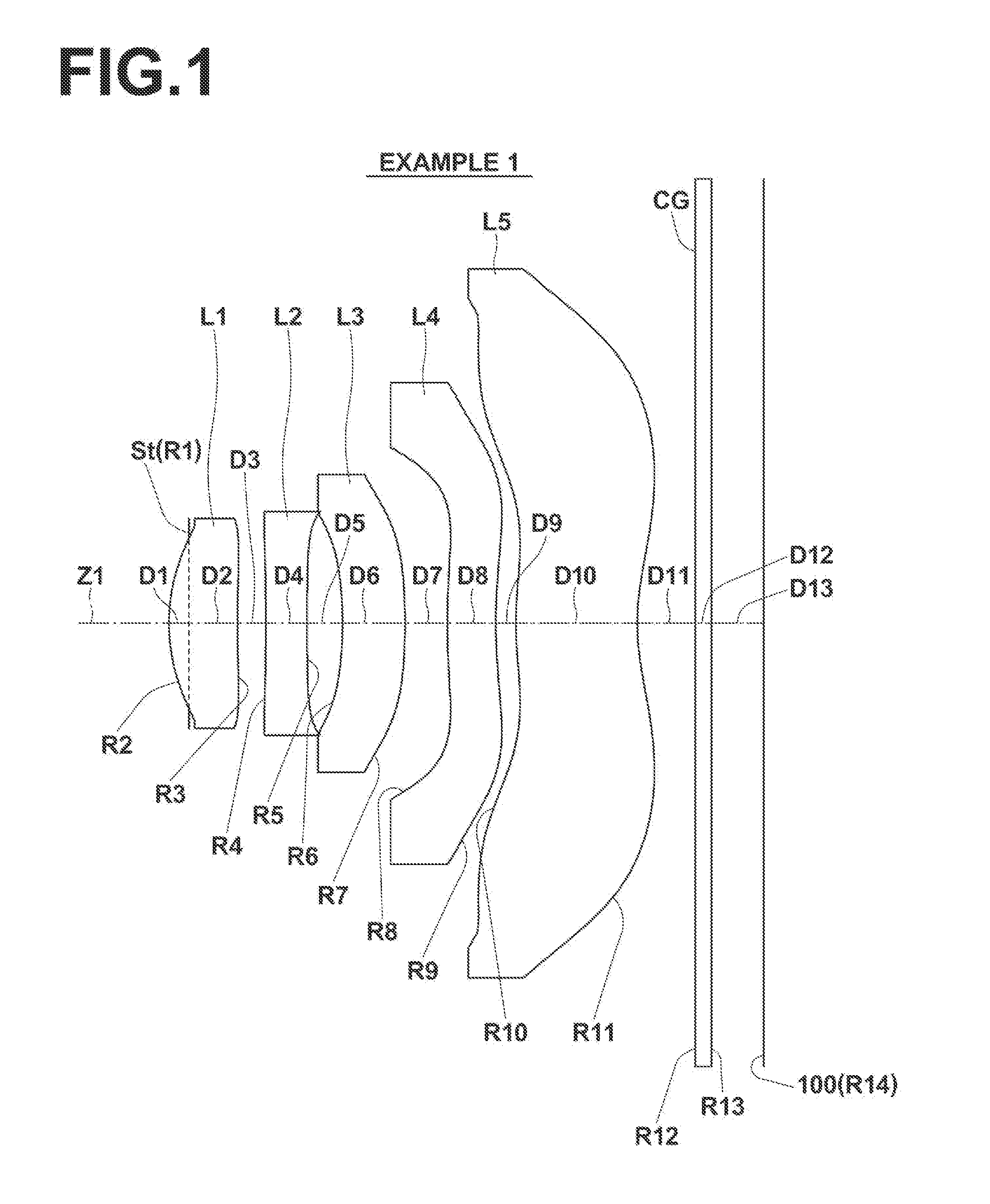
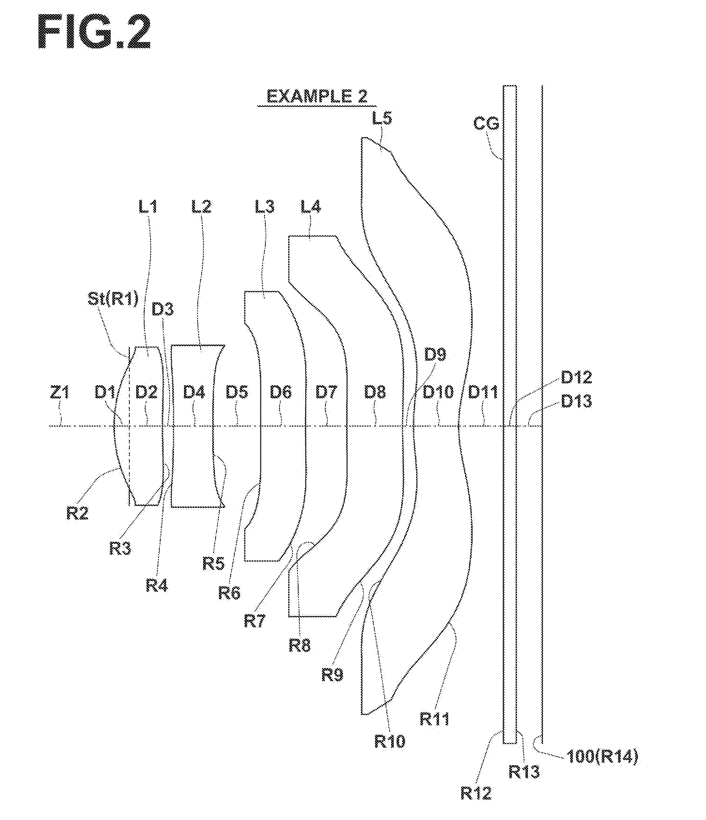
[0062]FIG. 1 illustrates a first example of the configuration of an imaging lens according to an embodiment of the present invention. This example corresponds to the lens configuration of Numerical Example 1 (Table 1 and Table 2), to be described later. Similarly, FIG. 2 through FIG. 9 are sectional diagrams that illustrate second through ninth examples of lens configurations that correspond to Numerical Examples 2 through 9 (Table 3 through Table 18) to be described later. In FIGS. 1 through 9, the symbol Ri represents the radii of curvature of ith surfaces, i being lens surface numbers that sequentially increase from the object side to the image side (imaging side), with the surface of a lens element most toward the object side designated as first. The symbol Di represents the distances between an ith surface and an i+1st surface along an optical axis Z1. Not...


PUM


Abstract

An imaging lens is substantially constituted by five lenses, including: a first lens having a positive refractive power; a second lens having a negative refractive power; a third lens having a negative refractive power; a fourth lens having a negative refractive power; a fifth lens having a negative refractive power and an inflection point on the surface thereof toward the image side. All of the first lens through the fifth lens are single lenses, and the imaging lens satisfies predetermined conditional formulae.

Description

CROSS REFERENCE TO RELATED APPLICATIONS[0001]This application is a Continuation of PCT International Application No. PCT / JP2013 / 003251 filed on May 22, 2013, which claims priority under 35 U.S.C. §119(a) to Japanese Patent. Application No. 2012-117144 filed on May 23, 2012, U.S. Provisional Patent Application No. 61 / 660,001 filed on Jun. 15, 2012, and Japanese Patent Application No. 2013-097737 filed on May 7, 2013. Each of the above application(s) is hereby expressly incorporated by reference, in its entirety, into the present application.BACKGROUND OF THE INVENTION[0002]1. Technical Field[0003]The present invention is related to a fixed focus imaging lens for forming optical images of subjects onto an imaging element such as a CCD (Charge Coupled Device) and a CMOS (Complementary Metal Oxide Semiconductor). The present invention is also related to an imaging apparatus provided with the imaging lens that performs photography such as a digital still camera, a cellular telephone with...

Claims


Application Information

Patent Timeline
Patent Type & Authority Applications(United States)
IPC IPC(8): G02B13/00G02B9/60
CPCG02B9/60G02B13/0045G02B13/18
Inventor NODA, TAKAYUKICHO, MICHIO
Owner JIANGXI OFILM OPTICAL CO LTD
Why Eureka
Try Eureka