LED lighting device

a technology of led lighting and led light bulbs, which is applied in the direction of lighting support devices, semiconductor devices for light sources, lighting and heating apparatus, etc., can solve the problems of serious heat dissipation problems of light bulbs, and serious degradation of light output, and achieve the effect of high luminan

Active Publication Date: 2015-03-19
HUANG TAI YIN
View PDF11 Cites 10 Cited by
  • Summary
  • Abstract
  • Description
  • Claims
  • Application Information

AI Technical Summary

Benefits of technology

[0009]The objective of the present disclosure is to provide an LED light bulb having a specific structure for heat dissipation, thereby sa...

Problems solved by technology

However, even though a conventional LED light bulb has the abovementioned advantages, heat dissipation is problematic when high wattage is required for high illumination, leading to serious degradation of light output.
When higher wattages are to be...

Method used


Image

  • LED lighting device
  • LED lighting device
  • LED lighting device

Examples


first embodiment

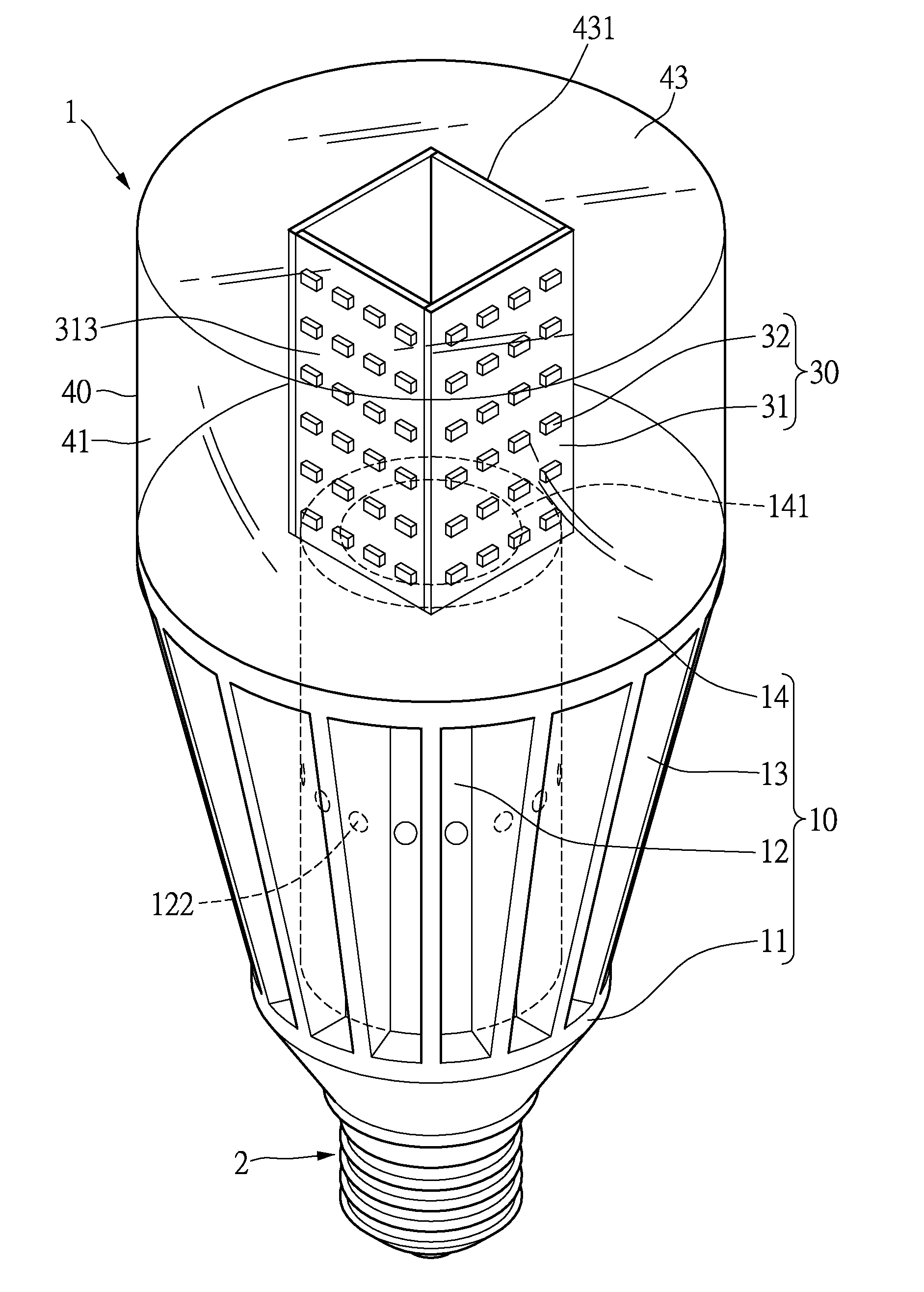
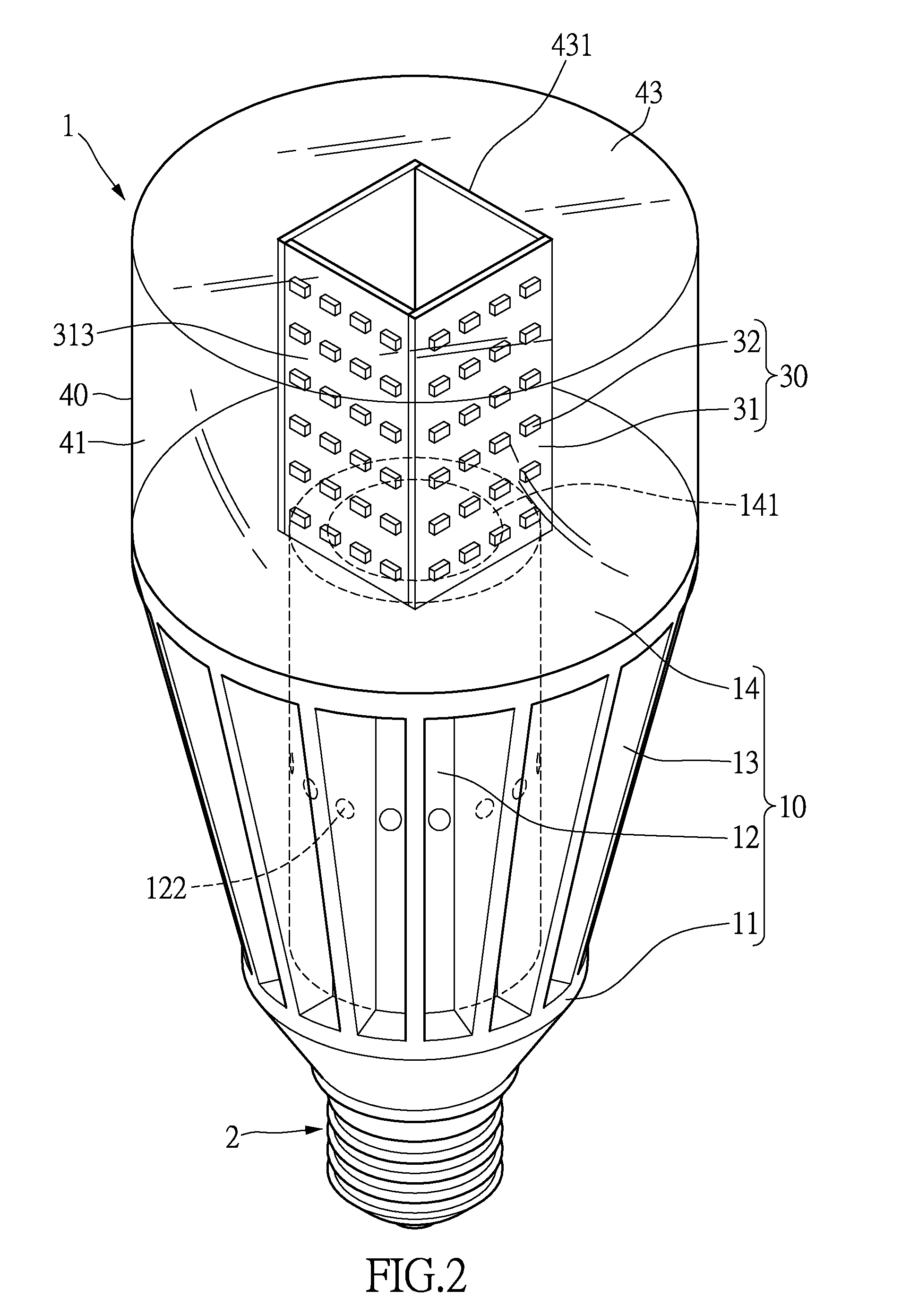
[0022]FIG. 2 shows an assembly view of an LED light bulb according to a first embodiment of the present disclosure. FIG. 3 shows a cross-section view of an LED light bulb according to a first embodiment of the present disclosure. The present embodiment provides an LED lighting device 1 connected to a cap 2. The LED lighting device 1 includes a heat dissipation body 10, a driver module 20 and a lighting module 30. The heat dissipation body 10 and the lighting module 30 of the present disclosure have specific structures for increasing heat dissipation, thereby achieving the objective of increasing wattage and increasing luminance. The following describes the structure of the LED lighting device 1.

[0023]The heat dissipation body 10 includes a base 11, a heat dissipation wall 12, a plurality of heat dissipation fins 13, and a top face 14. The base 11 of the heat dissipation body 10 can be a board connected to the cap 2. The heat dissipation wall 12 can be a tubular structure enclosing a...

second embodiment

[0031]FIG. 3 shows a cross-section view of an LED light bulb according to a first embodiment of the present disclosure. FIG. 4 shows an assembly view of an LED light bulb according to a second embodiment of the present disclosure. The difference between the present embodiment and the above embodiment lies in that the heat dissipation body 10 further comprises a partition board 15 connected to the heat dissipation wall 12 for improving the waterproof effect of the present disclosure.

[0032]Specifically, the partition board 15 partitions the heat dissipation wall 12 into a first section positioned above and a second section 124 positioned below. The top face 14 of the heat dissipation body 10, the first section 123 of the heat dissipation wall 12 and the partition board 15 define a first space 1211 in the heat dissipation channel 121. The first through holes 122 of the heat dissipation wall 12 are arranged at the first section 123. By this configuration, the first through holes 122 not...

third embodiment

[0034]FIG. 6 shows a schematic diagram of a portion of an LED light bulb according to a third embodiment of the present disclosure. The main difference between the present embodiment and the above embodiment lies in that the tube body 31 has a ventilation cover 3121 disposed at the end opening 312 at the transparent cover 40. The ventilation cover 3121 can be a grid with through holes therein. In another preferred embodiment, the ventilation board 3121 can be arranged at the second opening (not shown) of the transparent cover 40. By this configuration, the ventilation board 3121 can prevent insects from flying into the LED lighting device 1 while being air permeable.

[0035]Of particular note, the language of upper, lower, left, right, front, rear, etc. only reference the directions as shown in the figures. Therefore, the directions are not meant to limit the present disclosure.

[0036]In summary of the above, the LED lighting device of the present disclosure has the following advantage...


PUM


Abstract

The present disclosure provides an LED lighting device comprising a heat dissipation body, a driver module and a lighting module. The heat dissipation body includes a base, a heat dissipation wall, heat dissipation fins and a top face. The heat dissipation wall defines a heat dissipation channel therein and is formed with first through holes. The heat dissipation fins are formed on and encircle the heat dissipation wall. The top face is formed with a first opening The driver module is disposed inside the heat dissipation body. The lighting module includes a tube body and LED light sources. The tube body has two end openings in fluid communication with each other and one of the end openings is connected to the first opening The LED light sources are arranged on the tube body and are electrically connected to the driver module.

Description

BACKGROUND OF THE INVENTION[0001]1. Field of the Invention[0002]The present disclosure relates to an LED light bulb; in particular, to an LED light bulb having good heat dissipating effect.[0003]2. Description of Related Art[0004]With increasing awareness to environmentalism, light-emitting diode (LED) lamps having high energy efficiency and long life span have become more popular and have replaced traditional incandescent light bulbs as the mainstream product on the market.[0005]Referring to FIG. 1, an LED light bulb la includes a cap 10a and at least three light-emitting modules 20a. Each of the light-emitting modules 20a includes a substrate 21a. A plurality of LED chips 22a are disposed on the two sides of each of the substrates 21a. The LED chips 22a are electrically connected to the cap 10a through the substrates 21a. [0006]However, even though a conventional LED light bulb has the abovementioned advantages, heat dissipation is problematic when high wattage is required for hig...

Claims


Application Information

Patent Timeline
IPC IPC(8): F21V29/00F21V23/00F21K99/00
CPCF21V29/262F21K9/1355F21Y2101/02F21V29/2218F21V23/003F21V29/2293F21V3/02F21V29/506F21V29/74F21V29/83F21K9/23F21Y2115/10F21Y2107/30F21K9/238F21V29/508
Inventor SUN, TSENG-BAO
Owner HUANG TAI YIN
Why Eureka
Try Eureka