Method, computer program product & system

a technology of rolling-element bearings and computer programs, applied in the direction of instruments, force/torque/work measurement, instruments, etc., can solve the problems of progressive flaking or pitting of the surfaces of rolling-elements and surfaces, significant commercial loss to the end-user, and excessive heat, pressure and friction

Inactive Publication Date: 2015-03-19
AB SKF
View PDF3 Cites 13 Cited by
  • Summary
  • Abstract
  • Description
  • Claims
  • Application Information

AI Technical Summary

Benefits of technology

[0010]An object of the invention is to provide an improved method for predicting the residual life of a rolling-element bearing.

Problems solved by technology

Rolling-element bearings are often used in critical applications, wherein their failure in service would result in significant commercial loss to the end-user.
Fatigue failure of a rolling-element bearing results from progressive flaking or pitting of the surfaces of the rolling-elements and of the surfaces of the corresponding bearing races.
The flaking and pitting may cause seizure of one or more of the rolling-elements, which in turn may generate excessive heat, pressure and friction.
However, this type of life prediction is considered inadequate for the purpose of maintenance planning for several reasons.
Another reason is that a bearing's residual life may be radically compromised by short-duration events or unplanned events, such as overloads, lubrication failures, installation errors, etc.
Yet another reason is that, even if nominal operating conditions are accurately reproduced in service, the inherently random character of the fatigue process may give rise to large statistical variations in the actual residual life of substantially identical bearings.

Method used


Image

  • Method, computer program product & system
  • Method, computer program product & system
  • Method, computer program product & system

Examples


Embodiment Construction

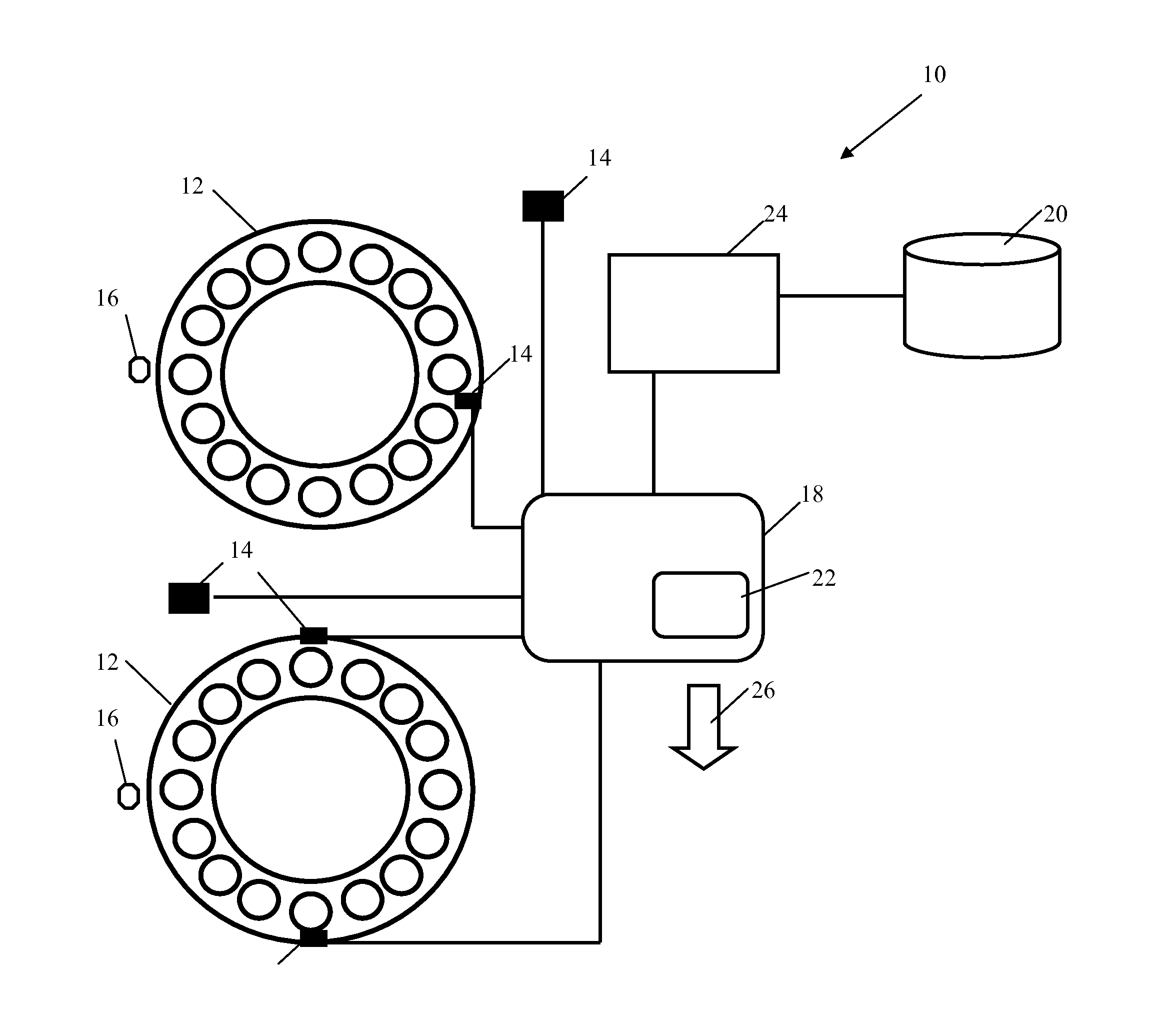
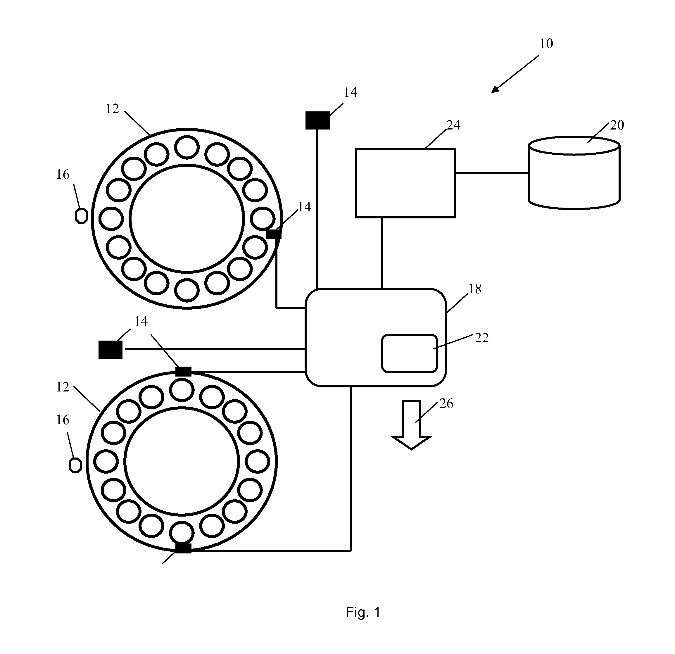
[0040]FIG. 1 shows a system 10 for predicting the residual life of a plurality of rolling-element bearings 12 during their use. The illustrated embodiment shows two rolling-element bearings 12, the system 10 according to the present invention may however be used to predict the residual life of one or more rolling-element bearings 12 of any type, and not necessarily all of the same type or size. The system 10 comprises a plurality of sensors 14 configured to measure contact forces and / or high frequency stress waves emitted by rolling contact of the rolling-element bearings 12. A sensor 14 may be integrated with a rolling-element bearing 12 or it may be placed in the vicinity of the rolling-element bearing 12.

[0041]Rolling contact forces may for example be recorded by a strain sensor 14 located on an outer surface or side of the bearing's outer ring, or on an inner surface or inner side of the bearing's inner ring. Such a strain sensor 14 could be of the resistance type or use the str...


PUM

PropertyMeasurementUnit
residual lifeaaaaaaaaaa
contact forcesaaaaaaaaaa
frequencyaaaaaaaaaa

Abstract

A method for predicting the residual life of a bearing comprising the steps of measuring contact forces and/or high frequency stress waves emitted by rolling contact of the bearing, recording the measurement data as recorded data, and predicting the residual life of the bearing using the recorded data and an International Organization for Standardization (ISO) bearing life model whereby load is determined from measurements of contact forces and/or lubrication quality is determined from the high frequency stress waves emitted by rolling contact, rather than by the International Organization for Standardization (ISO) rolling-element bearing life model.

Description

CROSS REFERENCE TO RELATED APPLICATIONS[0001]This is a National Stage application claiming the benefit of International Application Number PCT / EP2013 / 056492 filed on 27 Mar. 2013 (27 Mar. 2013), which claims the benefit of U.S. Provisional Patent Application No. 61 / 637,523 filed on 24 Apr. 2012 (24 Apr. 2013) and U.S. Provisional Patent Application No. 61 / 637,568 filed on 24 Apr. 2012 (24 Apr. 2012), all of which are incorporated herein by reference in their entireties.TECHNICAL FIELD[0002]The present invention concerns a method, system and computer program product for predicting the residual life of a rolling-element bearing, i.e. for predicting when it is necessary or desirable to service, replace or refurbish (re-manufacture) the rolling-element bearing.BACKGROUND OF THE INVENTION[0003]Rolling-element bearings are often used in critical applications, wherein their failure in service would result in significant commercial loss to the end-user. It is therefore important to be able ...

Claims


Application Information

Patent Timeline
Patent Type & Authority Applications(United States)
IPC IPC(8): G01M13/04G01N3/00
CPCG01N3/00G01M13/04G07C3/00F16C41/004F16C19/522F16C19/525F16C19/527F16C2202/36F16C41/008F16C2233/00Y02E10/72G16Z99/00G01H17/00F16C41/00G01K13/00G01L5/00G01N17/00G01N3/56H02N11/00G01D21/02G01M13/045
Inventor HAMILTON, KEITHMURRAY, BRIAN
Owner AB SKF
Why Eureka
Try Eureka