Apparatus for acoustic damping and operational control of damping, cooling, and emissions in a gas turbine engine

Inactive Publication Date: 2015-03-26
SIEMENS AG
View PDF23 Cites 27 Cited by
  • Summary
  • Abstract
  • Description
  • Claims
  • Application Information

AI Technical Summary

Problems solved by technology

It is so great that film cooling can overshoot and separate from the hot inner surface of the duct, reducing cooling effectiveness, unless the cooling holes are kept smaller than in prior designs and smaller than is ideal.
Smaller holes clog with particles more quickly.
Space limitations can limit the size of damping resonators, thus li

Method used


Image

  • Apparatus for acoustic damping and operational control of damping, cooling, and emissions in a gas turbine engine
  • Apparatus for acoustic damping and operational control of damping, cooling, and emissions in a gas turbine engine
  • Apparatus for acoustic damping and operational control of damping, cooling, and emissions in a gas turbine engine

Examples


Embodiment Construction

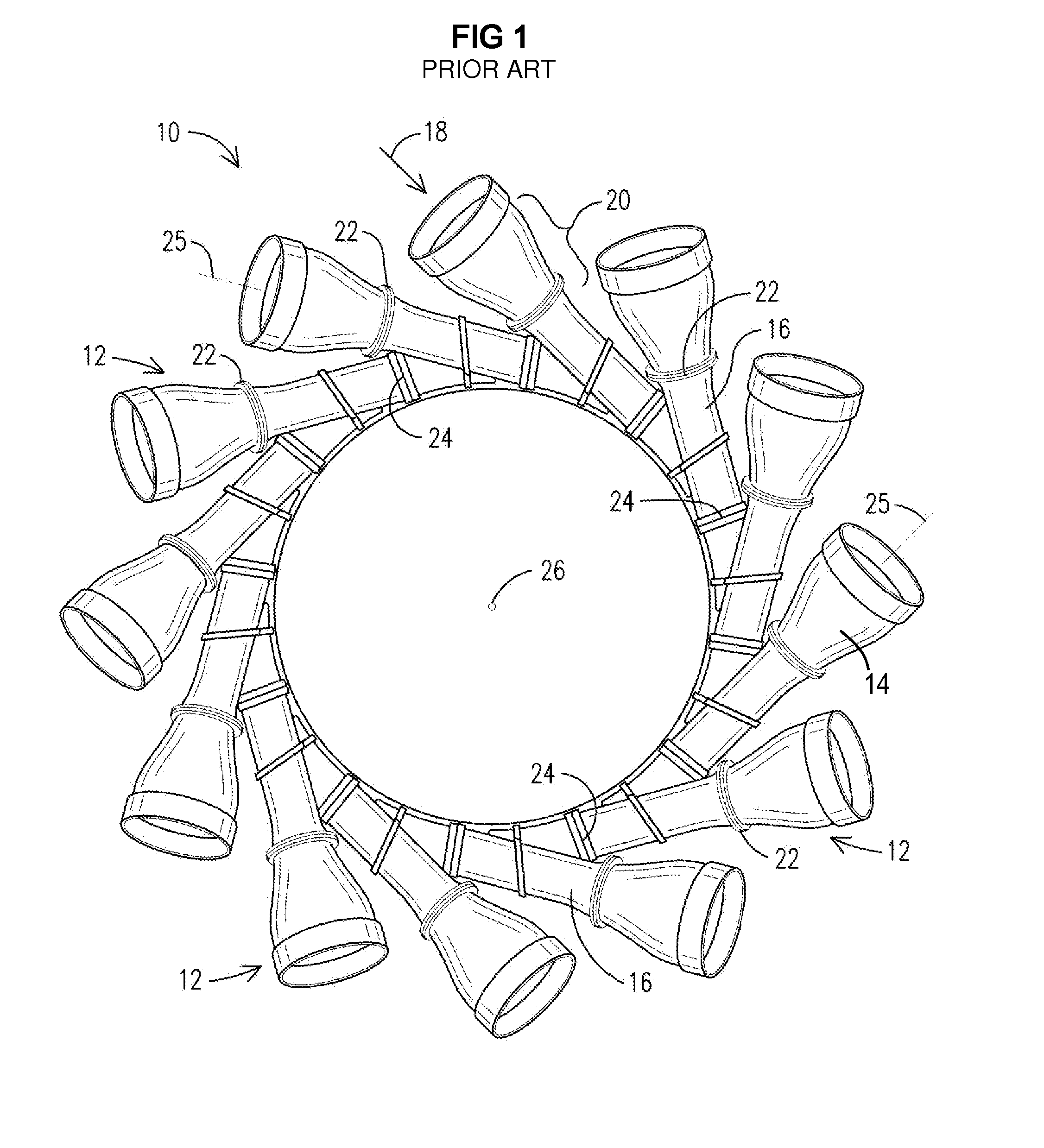
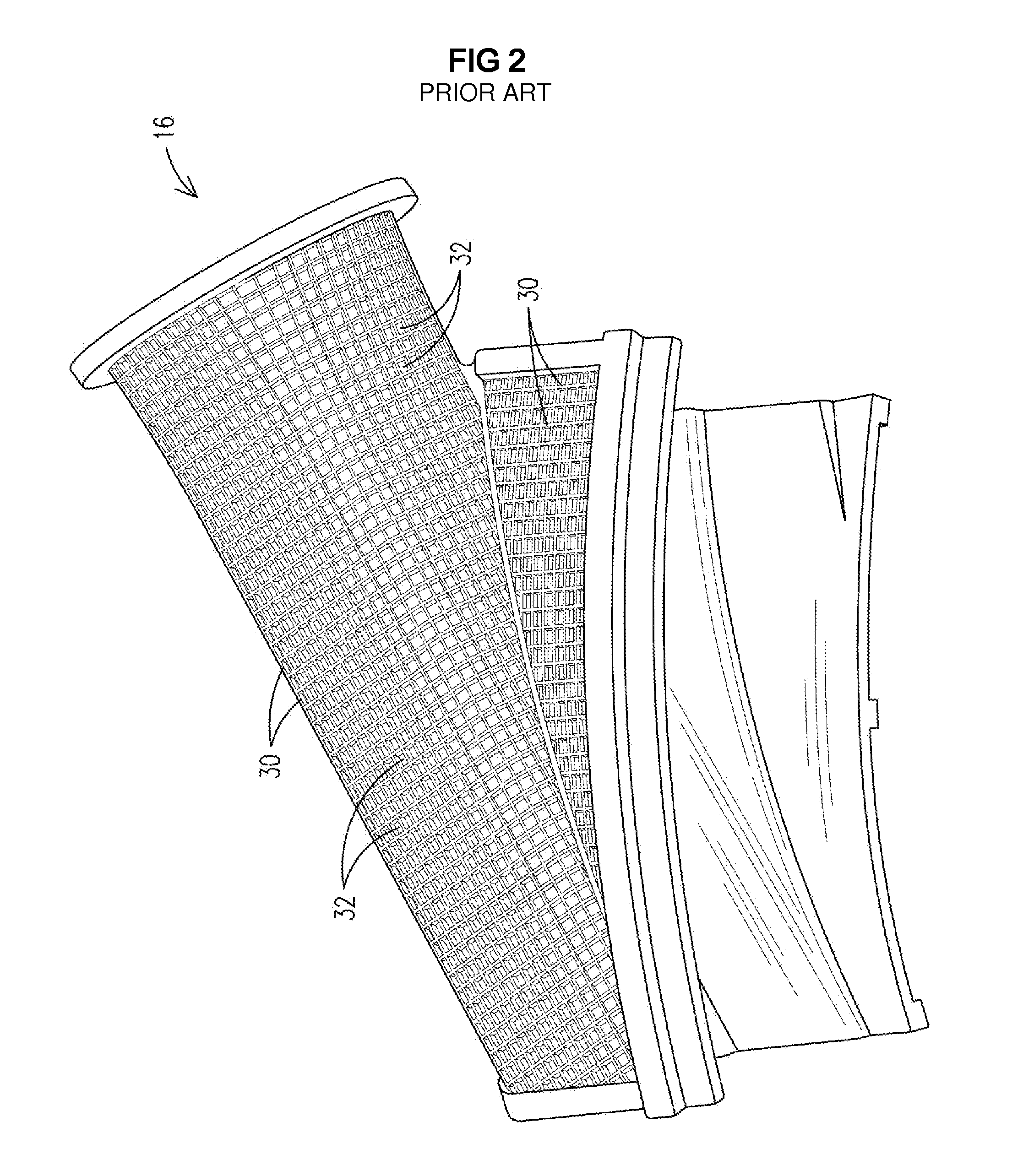
[0018]FIG. 1 shows an assembly 10 with a plurality of flow directing structures 12. Each flow directing structure 12 may include a cone 14 and an associated exit piece 16. Each cone 14 receives combustion gas 18 from a respective combustor (not shown), and begins accelerating the combustion gas 18 to a speed appropriate for delivery onto the first row of turbine blades (not shown). Acceleration of the combustion gas 18 is accomplished by an acceleration geometry 20 using flow cross section constriction based on the Bernoulli principle and the Venturi effect. In the example shown, this is embodied as a cone-shaped duct 14 with a centerline 25 oriented mainly tangentially and partly axially relative to the turbine axis 26. The cone 14 may abut the exit piece 16 at a joint 22. Adjacent exit pieces abut each other at joints 24. The exit pieces form an annular chamber immediately upstream of the first row of turbine blades (not shown). Combustion gas 18 enters each cone 14 and travels al...


PUM


Abstract

Acoustic damping resonators (60, 62, 76, 78) formed in pockets (32) between reinforcing ribs (30) in a grid of ribs on the outer surface of a wall (74) surrounding a combustion gas flow path (18). Each resonator has a perforated cover plate (64A-C) spanning between sides formed by the ribs (30). Film cooling exit holes (44) are provided in the wall (74) under each resonator. Resonating chambers (48A-C) of different volumes may be provided on the wall to damp different unwanted frequencies. Different sets of resonators with different volumes may be separately controlled by respective airflow control manifolds (66) via throttle valves (68, T1-T3). Control logic (70) may control the valves based on frequency/airflow response functions (80, 82) for each size of resonator to optimize damping and cooling and to lower emissions over varying engine operating conditions.

Description

FIELD OF THE INVENTION[0001]The invention relates to an apparatus for acoustic damping of a range of acoustic frequencies, and for operational control that optimizes acoustic damping, cooling, and emission control in a combustion section of a gas turbine engine.BACKGROUND OF THE INVENTION[0002]Gas turbine engines often use a portion of air from the compressor for cooling and emissions control. Combustion gas temperatures can approach or exceed limits for structures in the working gas flow path. Therefore, cooling of surfaces adjacent the combustion gas (“hot surface”) may be implemented. Film / effusion cooling holes are provided through walls of flow-directing structures lining the working gas flow path so that a portion of the compressed air bypasses the combustor inlets and flows through these walls. This approach is used on such structures as the combustion chamber liner, transition ducts, transition exit pieces, and other components. The holes provide film cooling and effusion co...

Claims


Application Information

Patent Timeline
IPC IPC(8): F23R3/16
CPCF23R3/16F01D9/023F02K1/827F05D2260/202F05D2260/963F23R2900/00014F05D2260/96
Inventor SCHILP, REINHARD
Owner SIEMENS AG
Why Eureka
Try Eureka