Igniter, igniter control method, and internal combustion engine ignition apparatus

a technology of internal combustion engine and control method, which is applied in the direction of electric ignition installation, mechanical equipment, machines/engines, etc., can solve the problems of increased loss of igniter, and increased loss of collector current, so as to reduce the size of igniter, prevent overshoot of collector current, and small size

Active Publication Date: 2015-03-26
FUJI ELECTRIC CO LTD
View PDF4 Cites 14 Cited by
  • Summary
  • Abstract
  • Description
  • Claims
  • Application Information

AI Technical Summary

Benefits of technology

[0063]According to the igniter, the igniter control method, and the internal combustion engine ignition apparatus of embodiments of the invention, it is possible to prevent the overshoot of a collector current of a main IGBT when a current is limited, without providing a depression IGBT.
[0064]Furthermore, according to the igniter, the igniter control method, and the internal combustion engine ignition apparatus of embodiments of the invention, since a depression IGBT is not provided, it is possible to reduce the size of an igniter. In addition, it is possible to provide an internal combustion engine ignition apparatus which has a small size, can suppress the overshoot of a collector current of a main IGBT, and can prevent an ignition error.

Problems solved by technology

However, the sum of a saturation voltage VCE (sat) between the collector and the emitter and a voltage which is generated by the shunt resistor for current detection increases, which results in an increase in the loss of the igniter.
The voltage of the spark plug is higher than a discharge voltage according to the collector voltage during the oscillation, which causes an ignition error.
Therefore, the collector voltage oscillates with a large amplitude and an ignition error occurs in the spark plug.
However, the above-mentioned techniques according to the related art have the following problems.
However, in the case in which the depression IGBT 20 is not provided, as described above, when an error occurs, that is, when overcurrent flows to the collector electrode, it is difficult to prevent a reduction in the collector current Ic and a rapid increase in the collector voltage VCE caused by the reduction in collector current Ic.

Method used


Image

  • Igniter, igniter control method, and internal combustion engine ignition apparatus
  • Igniter, igniter control method, and internal combustion engine ignition apparatus
  • Igniter, igniter control method, and internal combustion engine ignition apparatus

Examples


embodiment 1

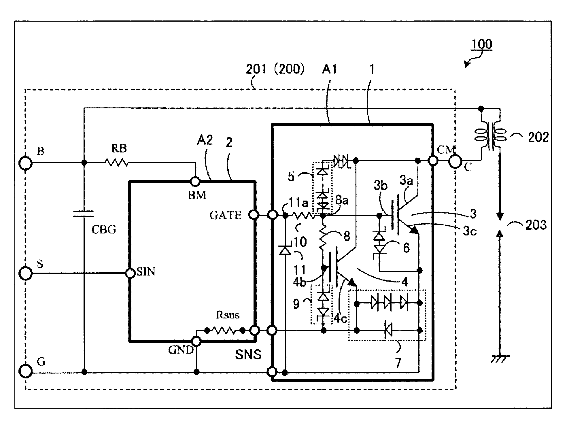
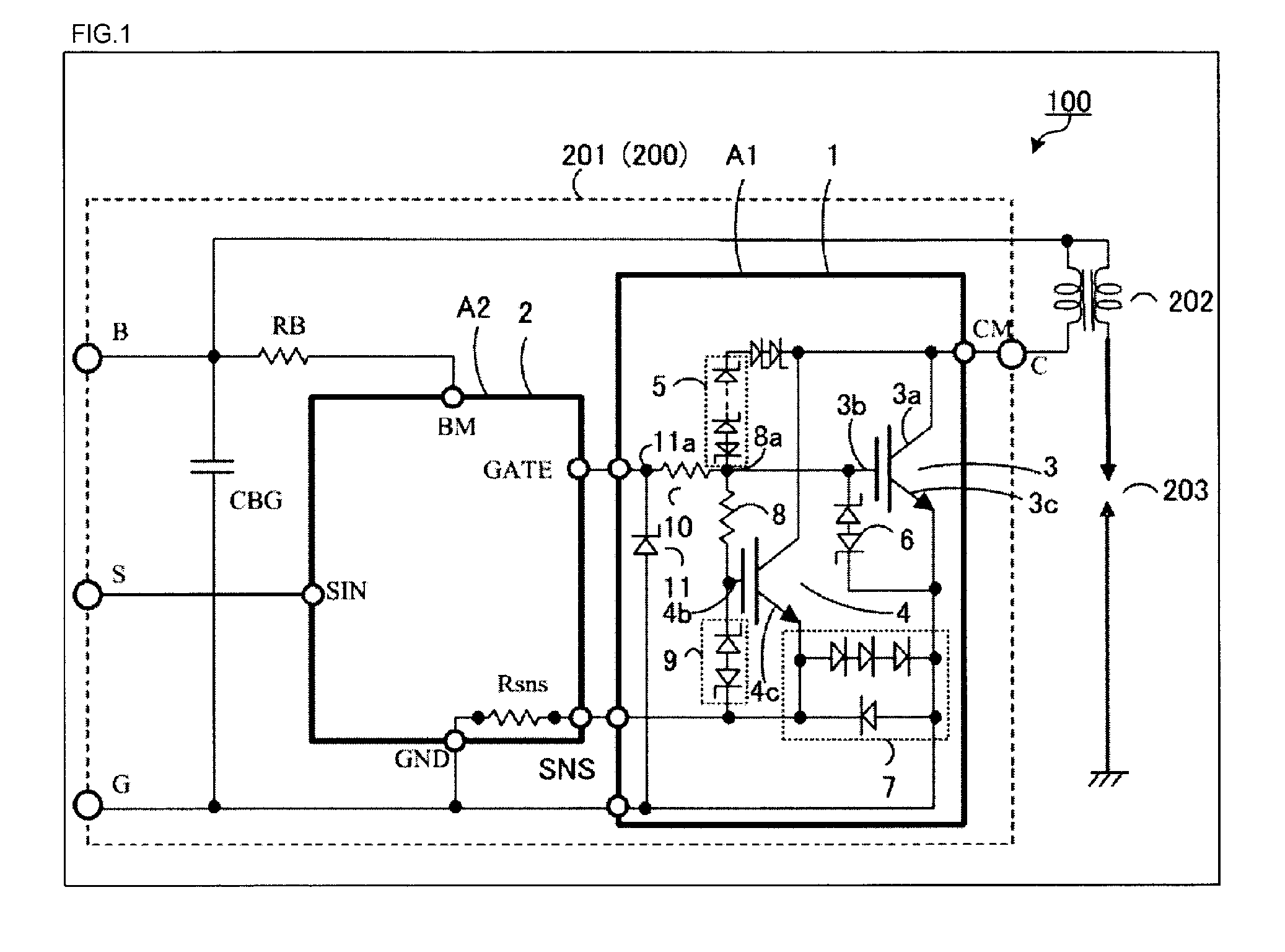
[0084]The structure of an internal combustion engine ignition apparatus according to Embodiment 1 will be described. FIG. 1 is a circuit diagram illustrating the circuit structure of a main portion of an internal combustion engine ignition apparatus 100 according to Embodiment 1 of the invention. FIG. 1 also illustrates the main circuit of a multi-chip igniter 201 which is provided in the internal combustion engine ignition apparatus 100. In this embodiment, a main IGBT 3 and a sense IGBT 4 are given as examples of elements forming an IGBT unit 1 and may be insulated gate field effect transistors (MOSFET: metal oxide semiconductor field effect transistors). In this case, an n+ drain layer (sixth semiconductor layer) and a drain electrode (third main electrode) may be provided instead of a p+ collector layer and a collector electrode, which will be described below. In addition, the multi-chip igniter 201 is a kind of igniter 200 and includes two semiconductor chips A1 and A2.

[0085]Th...

embodiment 2

[0145]Next, the structure of an internal combustion engine ignition apparatus according to Embodiment 2 will be described. FIG. 8 is a circuit diagram illustrating the structure of a main portion of an internal combustion engine ignition apparatus 300 according to Embodiment 2 of the invention. FIG. 8 also illustrates a circuit diagram illustrating a main portion of a one-chip igniter 401 provided in the internal combustion engine ignition apparatus 300.

[0146]The internal combustion engine ignition apparatus 300 according to Embodiment 2 differs from the internal combustion engine ignition apparatus 100 according to Embodiment 1 in that the IGBT unit 1 and the control IC unit 2 are formed on the same semiconductor substrate 30 (one semiconductor chip). In this case, the same effect as that in the multi-chip igniter 201 illustrated in FIG. 1 is obtained by the one-chip igniter 401 illustrated in FIG. 8.

[0147]The one-chip igniter 401 illustrated in FIG. 8 is provided in the internal c...


PUM


Abstract

An igniter is not provided with a depression IGBT and is configured such that a distance between a main IGBT and a sense IGBT is equal to or greater than 100 μm and equal to or less than 700 μm and preferably equal to or greater than 100 μm and equal to or less than 200 μm. The igniter is controlled such that, before the overcurrent of the main IGBT reaches a predetermined upper limit, a sense current of the sense IGBT is saturated. Therefore, it is possible to provide the igniter which has a small size and prevents the overshoot of a collector current of the main IGBT when a current is limited and an internal combustion engine ignition apparatus which includes the igniter, has a small size, and prevents an ignition error.

Description

CROSS-REFERENCE TO RELATED APPLICATIONS[0001]This is a continuation application, filed under 35 U.S.C. §111(a), of International Patent Application No. PCT / JP2013 / 073431 filed on Aug. 30, 2013, which claims the foreign benefit of Japanese Patent Application No. 2012-190385, filed on Aug. 30, 2012, and of Japanese Patent Application No. 2013-166406, filed Aug. 9, 2013, the disclosures of all of which are incorporated herein by reference.BACKGROUND[0002]1. Field[0003]The present disclosure relates to an igniter, an igniter control method, and an internal combustion engine ignition apparatus including the igniter.[0004]2. Description of Related Art[0005]There is an increasing demand for improving the “safety”, “comfort”, and “environmental performance” of vehicles. With an increase in the number of electronic components used in the vehicles, the number of semiconductors used per vehicle increases and there is a demand for an in-vehicle semiconductor device with “high reliability”, a “s...

Claims


Application Information

Patent Timeline
Patent Type & Authority Applications(United States)
IPC IPC(8): F02P3/055
CPCF02P3/0552F02P3/05H01L27/0203H01L29/7395F02P17/00H01L27/0825
Inventor NAITO, TATSUYA
Owner FUJI ELECTRIC CO LTD
Why Eureka
Try Eureka