System for controlling a synchronous electric motor

a technology of synchronous electric motors and control systems, applied in the direction of electronic commutation motor control, motor/generator/converter stoppers, dynamo-electric converter control, etc., can solve the problem of the need for sufficient decoupling of time scales and the difficulty of estimating the speed of the motor with an algorithm based on the current at the stator

Active Publication Date: 2015-03-26
SCHNEIDER TOSHIBA INVERTER EUROPE SAS
View PDF4 Cites 5 Cited by
  • Summary
  • Abstract
  • Description
  • Claims
  • Application Information

AI Technical Summary

Benefits of technology

[0008]According to a particular feature, the system comprises a safety block devised so as to compare the first speed and the second speed that are determined for the synchronous electric motor.

Problems solved by technology

When the synchronous electric motor rotates whilst the current at the stator is zero, the estimation of the speed of the motor with an algorithm based on the current at the stator may therefore turn out to be difficult.
One of the drawbacks of this scheme is the necessity for sufficient decoupling of the time scales (the injection must be fast with respect to the rotation frequency).

Method used


Image

  • System for controlling a synchronous electric motor
  • System for controlling a synchronous electric motor
  • System for controlling a synchronous electric motor

Examples


Embodiment Construction

[0015]The invention relates to a control system implemented in a variable speed drive for the control of a synchronous electric motor.

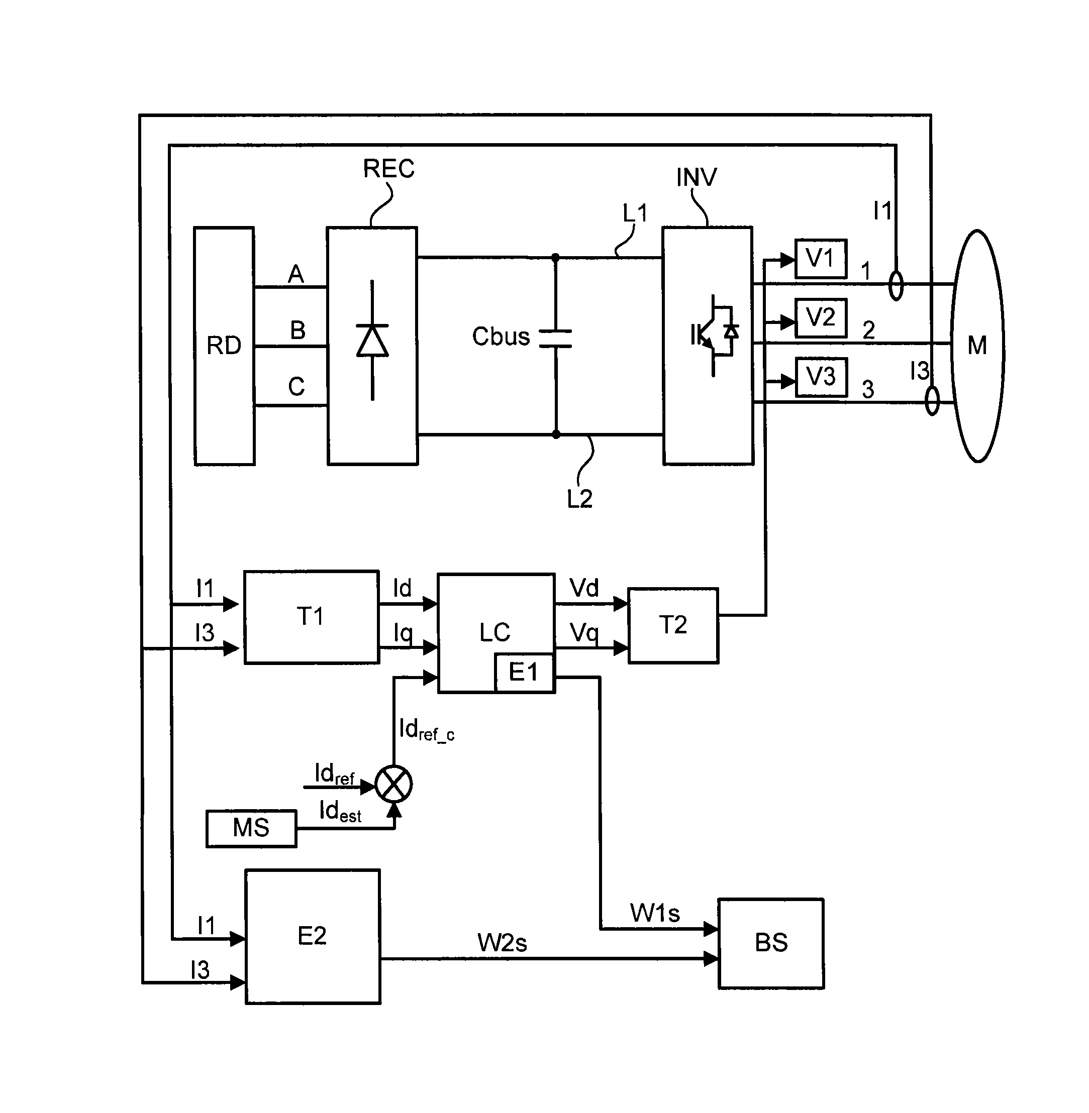
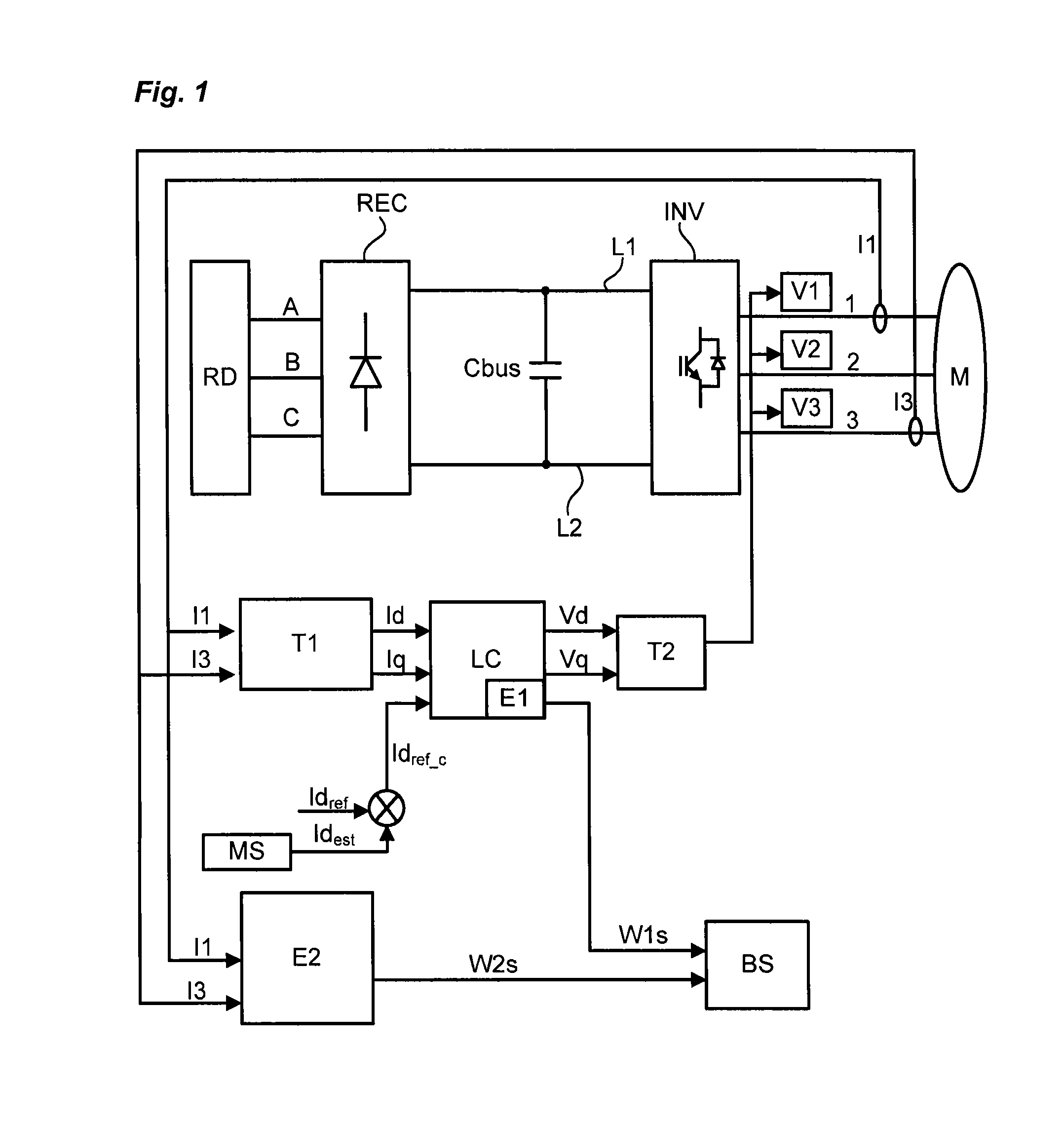
[0016]In a known manner, a variable speed drive comprises:[0017]three input phases A, B, C connected to an electrical distribution network RD,[0018]a rectifier module REC situated at input and intended to convert an AC voltage provided by the electrical distribution network RD into a DC voltage,[0019]a DC power supply bus connected, upstream, to the rectifier module REC and, downstream, to the inverter module INV and comprising two power supply lines L1, L2 between which the DC voltage is applied,[0020]a bus capacitor Cbus connected to the two power supply lines L1, L2 and charged with maintaining the DC voltage of the bus at a constant value,[0021]an inverter module INV connected by three output phases 1, 2, 3 to the synchronous electric motor M and controlled by control signals generated by a control unit implementing a determined control law LC. Th...


PUM


Abstract

A control system included in a speed selector connected by output phases to a synchronous electric motor, the synchronous electric motor being controlled according to a control law implemented by the speed selector. A first speed of the synchronous electric motor is determined by a first speed estimator. A second speed estimator is used to determine a second speed of the synchronous electric motor. The system includes a signal generator module configured to apply, to the output phases, voltages taking account of a non-constant current signal. The second speed estimator is configured to recover the current response on the output phases, to deduce therefrom the second speed of the synchronous electric motor.

Description

TECHNICAL FIELD OF THE INVENTION[0001]The present invention pertains to a control system implemented in a variable speed drive connected to a synchronous electric motor.PRIOR ART[0002]In a synchronous electric motor, with zero torque, the current at the stator of the motor is zero but the motor can continue to rotate and therefore have a non-zero speed. Within a context of functional safety, it is known to monitor the speed of an electric motor by executing two different, independent algorithms in redundancy mode. When the synchronous electric motor rotates whilst the current at the stator is zero, the estimation of the speed of the motor with an algorithm based on the current at the stator may therefore turn out to be difficult.[0003]Techniques with high-frequency injections make it possible to estimate the angle of the motor and therefore its rotation speed. Such is the case in patent application US2007 / 0236167A1. One of the drawbacks of this scheme is the necessity for sufficient...

Claims


Application Information

Patent Timeline
Patent Type & Authority Applications(United States)
IPC IPC(8): H02P6/08
CPCH02P6/08H02P21/24H02P21/18
Inventor DEFAIX, OLIVIERDEVOS, THOMAS
Owner SCHNEIDER TOSHIBA INVERTER EUROPE SAS
Why Eureka
Try Eureka