Wireless Signal Transmission in Magnetic Resonance Systems

a magnetic resonance system and wireless technology, applied in the field of wireless signal transmission in the magnetic resonance system, can solve the problems of limited investigation space within the mr system, longer treatment time, and higher treatment cost, and achieve the effect of substantially reducing the interference of other fields present in the mr system

Active Publication Date: 2015-03-26
SIEMENS HEALTHCARE GMBH
View PDF6 Cites 16 Cited by
  • Summary
  • Abstract
  • Description
  • Claims
  • Application Information

AI Technical Summary

Benefits of technology

[0009]One object is to indicate an improved method and a device for the wireless transmission of a measurement signal and / or a control signal between two functional components, in particular between a local coil and a local coil interface on the device side, of a MR system, that may reduce the aforementioned problems.
[0015]Through the encoding of the measurement signal and the control signal into a RF transmit signal with a predefined (e.g., previously selected, defined) orbital angular momentum, the RF transmit signal is provided with an additional property rendering it distinguishable from other RF signals in the same frequency range. The risk of interference is thus reduced. Signal transmissions using the orbital angular momentum thus also offer the possibility of making available a further multiplicity of further channel capacities along with the polarization. This increase in the channel capacity takes place without increasing the frequency range, so that, as will be subsequently explained, the data volume transmitted with a specific bandwidth may also be increased.
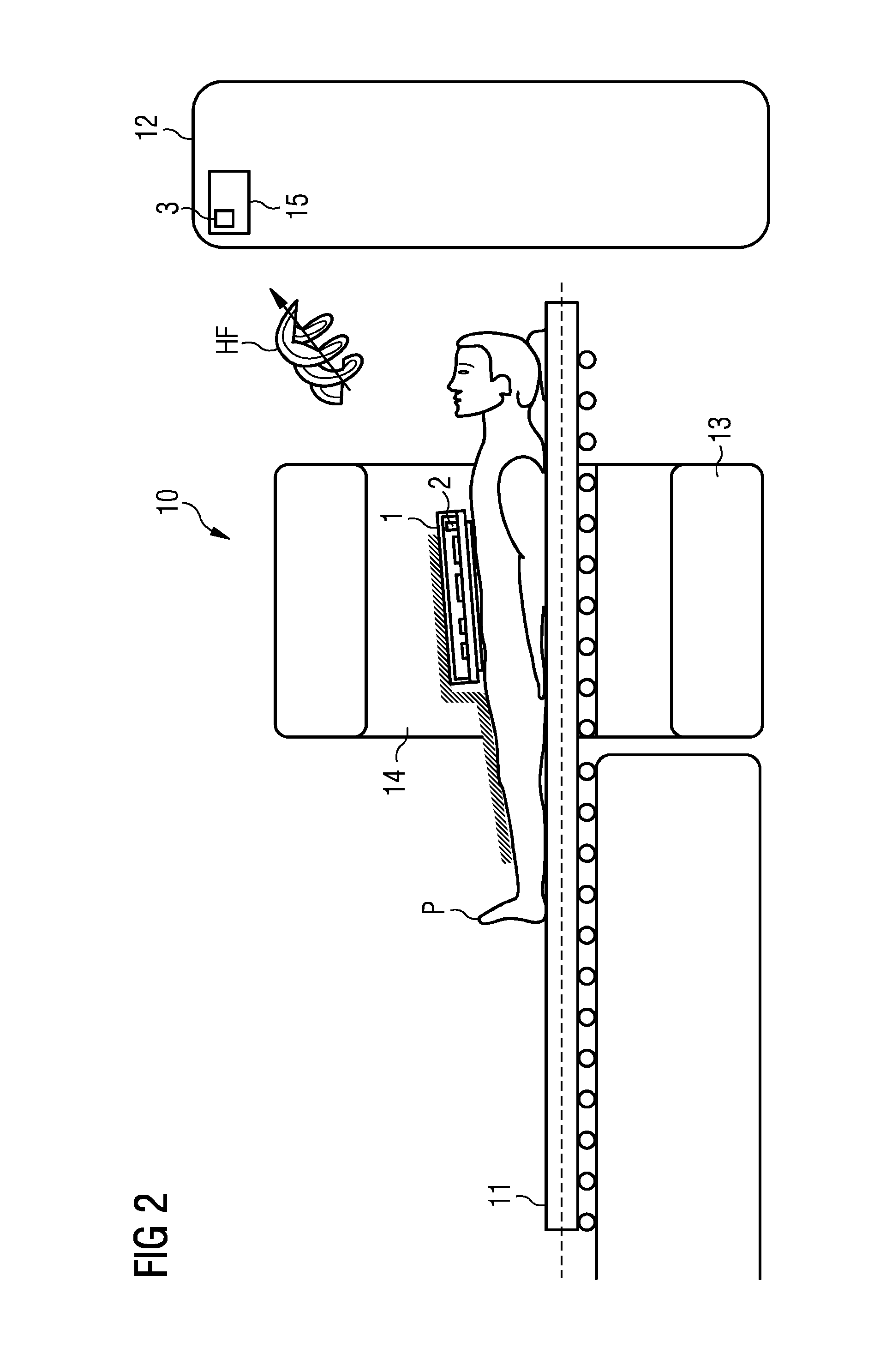
[0021]As mentioned, one of the functional components may include a local coil, and the second of the functional components a local coil interface on the device side of a MR system. The measurement signal may include a MR signal that is received by the MR antenna element array. In the local coil, a MR signal may be encoded onto a RF transmit signal provided with an orbital angular momentum. As mentioned, the orbital angular momentum encoding of the RF transmit signal offers the advantage that a unique allocation of the transmit channel is possible via the orbital angular momentum, by which the RF transmit signal of the local coil is rendered (additionally) distinguishable from other RF signals in the MR system and / or external RF signals.
[0022]RF transmit signals with different orbital angular momenta may be encoded in a multiplex method into a “mixed” RF transmit signal, (e.g., into a signal including a plurality of superposed orbital angular momenta), which may all be transmitted at the same frequency and at the same time. This offers the advantage that considerably more information may be transmitted, even without widening the frequency band.

Problems solved by technology

However, a multiplicity of cables slows down the attachment of the local coils to the object under examination, resulting in longer treatment times and therefore higher treatment costs.
Moreover, the investigation space within a MR system is limited, which limits the use of a multiplicity of cables, e.g., if the patient is moved on an associated bed facility.
The aforementioned restrictions apply particularly if analog response signals are transmitted by the MR antenna elements, since shielded (e.g., coaxial) cables may have a large cross section and a high weight and are expensive.
However, the wireless transmission has the disadvantage that a high bandwidth is required with the data volume to be transmitted and a multiplicity of transmit channels that are intended to be operated in parallel.
On the other hand, the available free bandwidth is small, since a multiplicity of electromagnetic signals already occurs in the range of MR systems.
With increasing bandwidth, the measures required to avoid disturbances, in particular electrical interference, over a very wide frequency range incur considerable cost.

Method used


Image

  • Wireless Signal Transmission in Magnetic Resonance Systems
  • Wireless Signal Transmission in Magnetic Resonance Systems
  • Wireless Signal Transmission in Magnetic Resonance Systems

Examples


Embodiment Construction

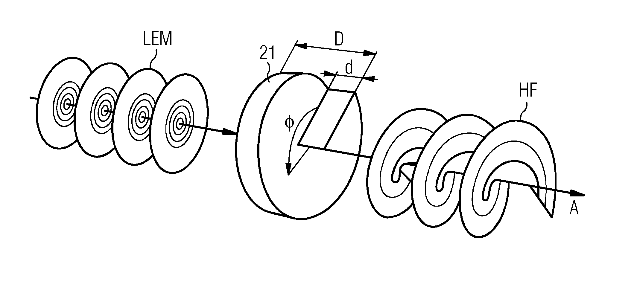
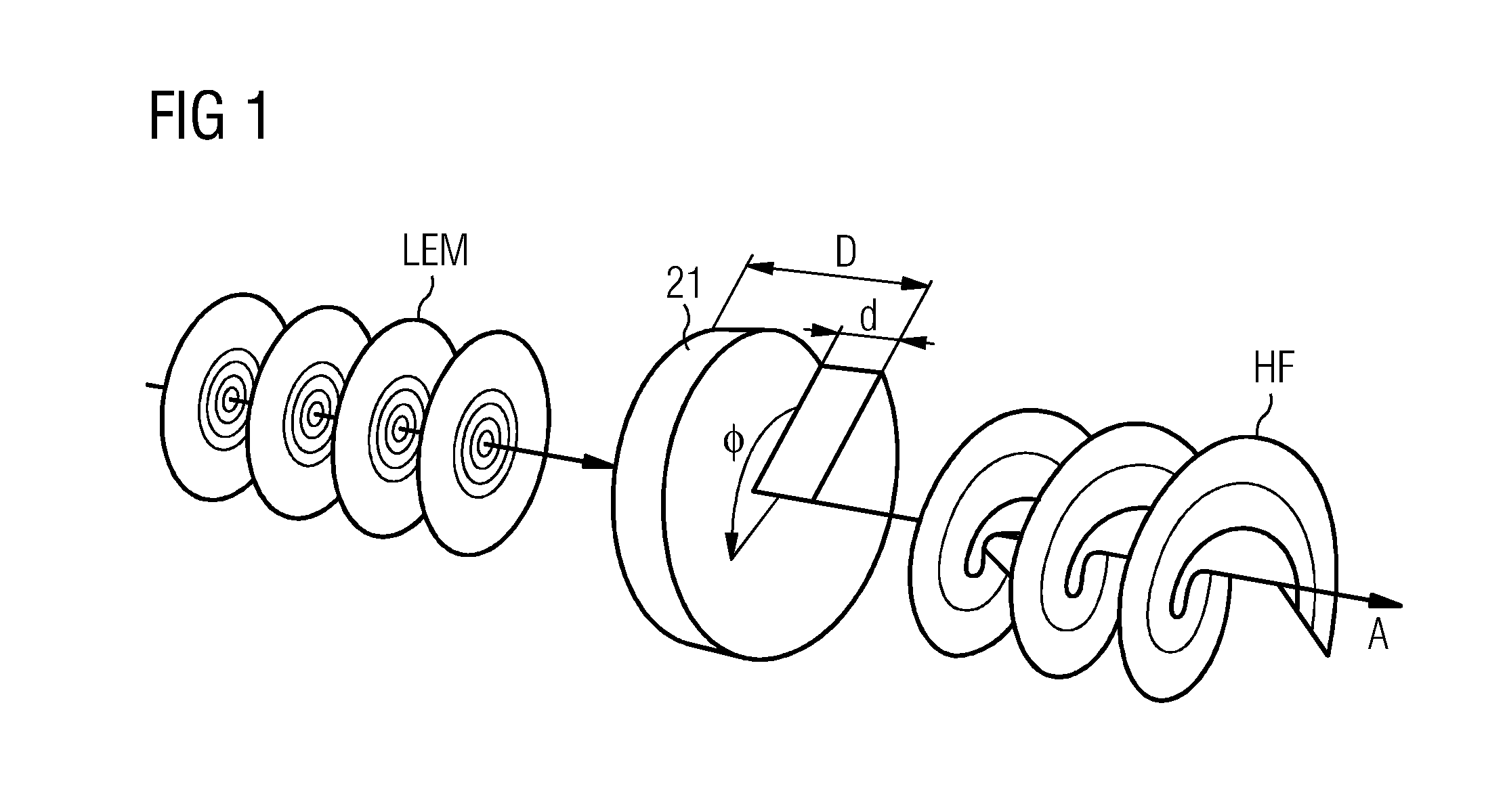
[0039]FIG. 1 depicts an electromagnetic wave RF with an orbital angular momentum I=1 in the right-hand part of the illustration that propagates helically in the direction of a virtual propagation axis A. It is evident that the energy density decreases substantially in the center of the direction of propagation A. The number of helices of the wave is directly proportional to the orbital angular momentum I. As depicted in FIG. 1, the electromagnetic wave RF having an orbital angular momentum is generated, in particular, from a linear-polarized electromagnetic wave LEM arriving from the left. This wave runs through a circular phase plate 21 that, coiled around a coil axis at the azimuthal angle Φ, has an increasing thickness, where the thickness is in each case constant along a radius. The coil axis runs parallel to the direction of propagation. Depending on the frequency range in which the RF transmit signal is to be modulated, a suitable material and the suitable maximum density D (e...


PUM


Abstract

A method is described for the wireless signal transmission of a measurement signal and / or a control signal between two functional components of a MR system. The measurement signal and / or the control signal is encoded into a RF transmit signal with a predefined orbital angular momentum and this RF transmit signal is transmitted between transmit antenna arrangements of the functional components. In addition, the embodiments relate to a local coil and an orbital angular momentum transmit unit with which the method may be carried out, and also a MR system that has a local coil and an orbital angular momentum transmit unit of this type.

Description

CROSS-REFERENCE TO RELATED APPLICATIONS[0001]This application claims the benefit of DE 10 2013 219 128.6, filed on Sep. 24, 2013, which is hereby incorporated by reference in its entirety.TECHNICAL FIELD[0002]The embodiments relate to methods for wireless signal transmission of a measurement signal and / or control signal between two functional components of a MR (magnetic resonance) system, which in each case have a transmit antenna arrangement. In addition, the embodiments relate to a local coil with a MR antenna element array for receiving and / or transmitting a MR signal. Furthermore, the embodiments relate to an orbital angular momentum transmit unit designed to receive and / or transmit RF transmit signals. Furthermore, the embodiments relate to a MR system including such a local coil and / or an orbital angular momentum transmit unit.BACKGROUND[0003]Today, medical technology imaging systems play an important role in the examination of patients. The representations of the internal or...

Claims


Application Information

Patent Timeline
Patent Type & Authority Applications(United States)
IPC IPC(8): G01R33/36H04B1/04G01R33/34
CPCG01R33/3692H04B1/0483G01R33/34G01R33/3415
Inventor POPESCU, STEFAN
Owner SIEMENS HEALTHCARE GMBH
Why Eureka
Try Eureka