Image display device, method of controlling image display device, computer program, and image display system
- Summary
- Abstract
- Description
- Claims
- Application Information
AI Technical Summary
Benefits of technology
Problems solved by technology
Method used
Image
Examples
first embodiment
A. First Embodiment
A-1. Configuration of an Image Display System
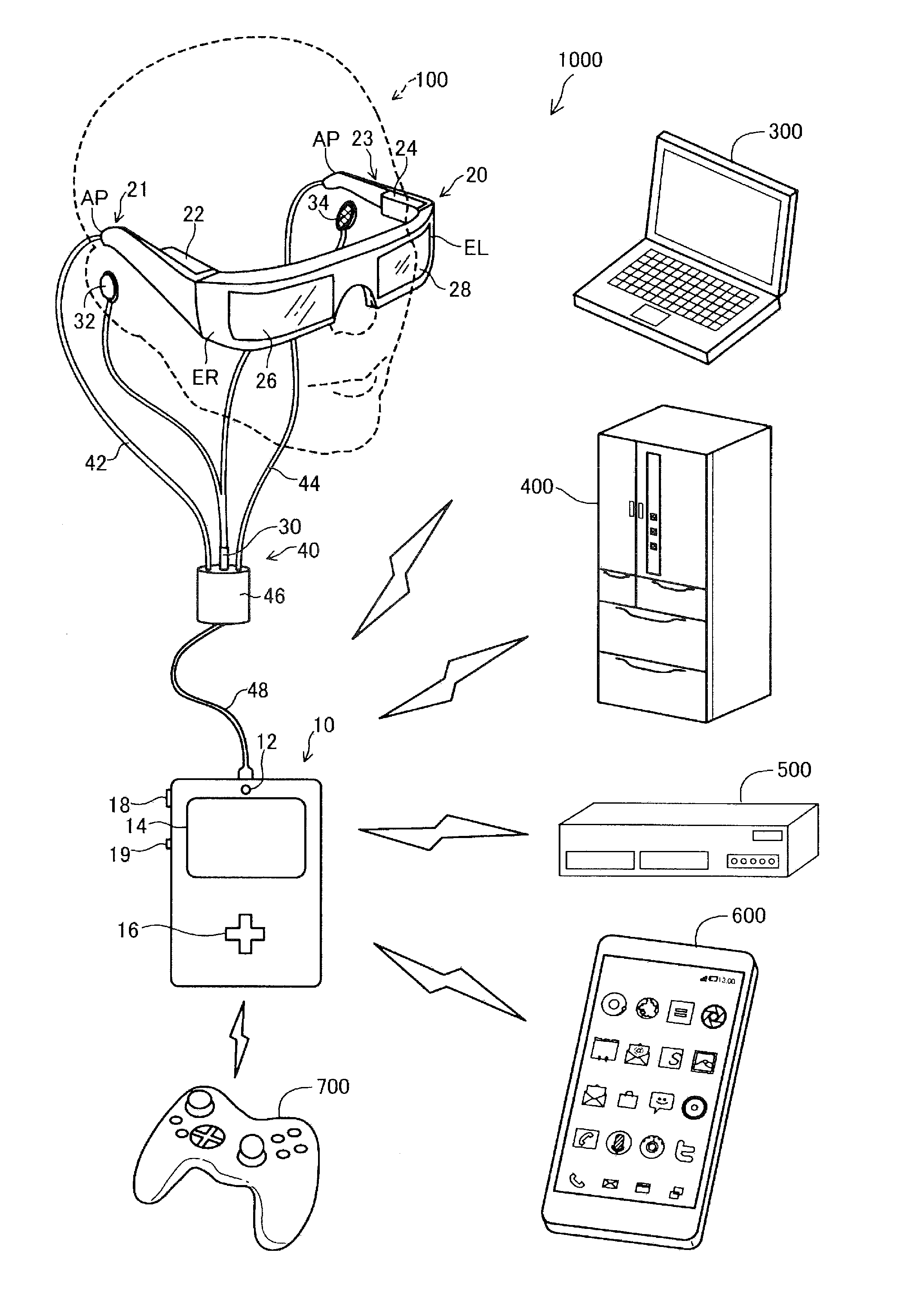
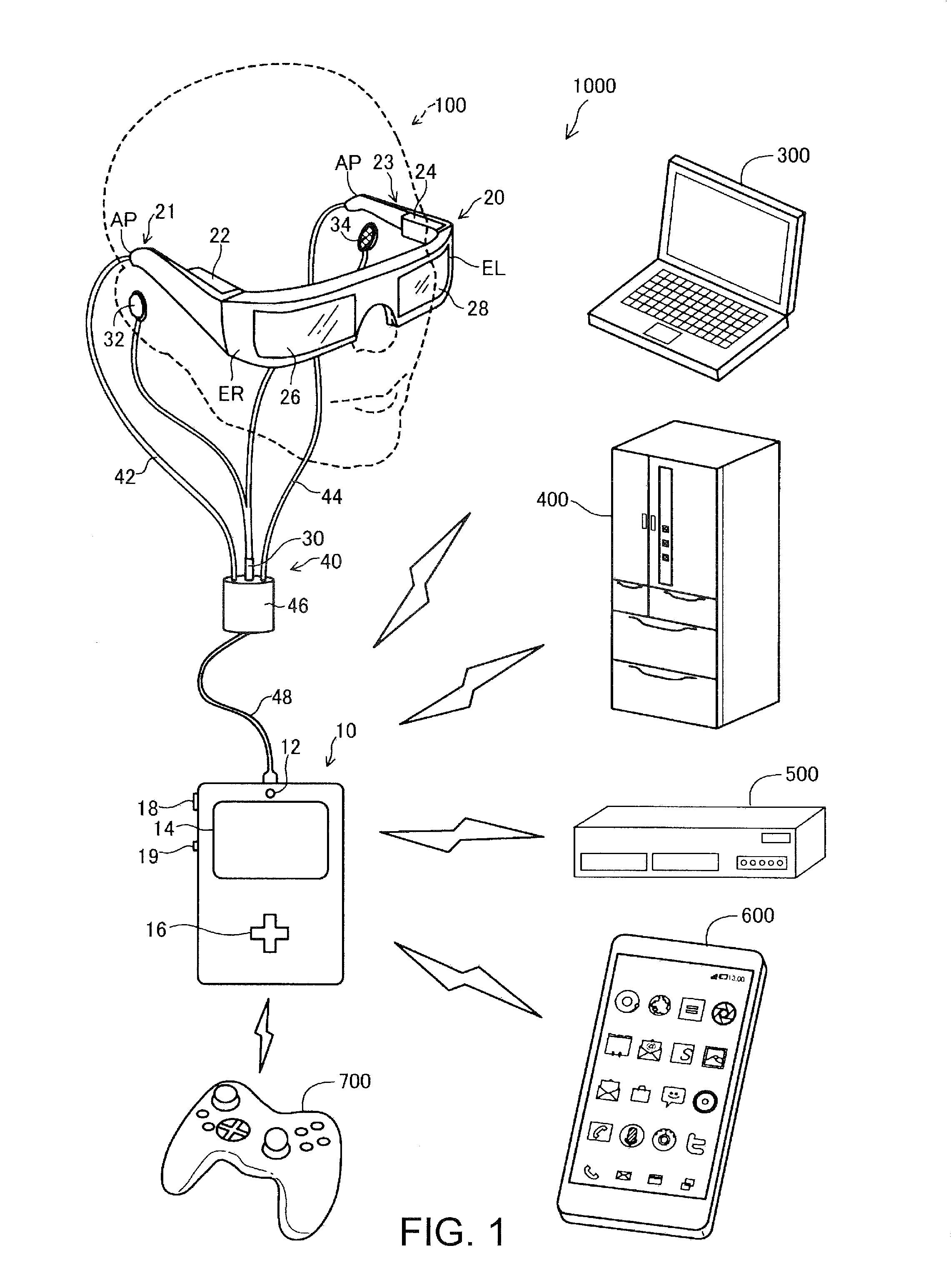
[0045]FIG. 1 is an explanatory diagram showing the schematic configuration of an image display system 1000 in an embodiment of the invention. The image display system 1000 includes a head mounted display 100, a computer 300 (PC 300), a home electric appliance 400, an AV (Audio Visual) device 500, a portable terminal 600, and a game device 700. In the following explanation, the head mounted display 100 is referred to as “image display device” as well. Similarly, the PC 300, the home electric appliance 400, the AV device 500, the portable terminal 600, and the game device 700 are collectively referred to as “external devices” as well. The image display system 1000 is a system that causes the head mounted display 100 to display an “integrated image” obtained by integrating displays in the external devices connected to the head mounted display 100.
[0046]The head mounted display 100 is an image display device mounted on the ...
second embodiment
B. Second Embodiment
[0120]In a second embodiment of the invention, a configuration is explained in which images of kinds different from the images exemplified in the first embodiment are used as identification images of an external device. In the following explanation, only components different from the components in the first embodiment in configurations and operations are explained. Note that, in the figures, components same as the components in the first embodiment are denoted by reference numerals and signs same as those in the first embodiment explained above. Detailed explanation of the components is omitted.
B-1. Configuration of an Image Display System
[0121]An image display system in the second embodiment is the same as the image display system in the first embodiment shown in FIG. 1 except that the image display system in the second embodiment includes a head mounted display 100a instead of the head mounted display 100.
B-2. Configuration of the Head Mounted Display
[0122]FIG....
third embodiment
C. Third Embodiment
[0146]In a third embodiment of the invention, a configuration is explained in which the thumbnail display regions B1 to B6 (the first display regions) of the integrated image are virtual display regions. In the following explanation, only components different from the components in the first embodiment in configurations and operations are explained. Note that, in the figures, components same as the components in the first embodiment are denoted by reference numerals and signs same as those in the first embodiment explained above. Detailed explanation of the components is omitted.
C-1. Configuration of an Image Display System
[0147]An image display system in the third embodiment is the same as the image display system in the first embodiment shown in FIG. 1 except that the image display system in the third embodiment includes a head mounted display 100b instead of the head mounted display 100.
C-2. Configuration of the Head Mounted Display
[0148]FIG. 14 is a functional...
PUM
 Abstract
Description
Claims
Application Information
 - R&D
- Intellectual Property
- Life Sciences
- Materials
- Tech Scout
- Unparalleled Data Quality
- Higher Quality Content
- 60% Fewer Hallucinations
Browse by: Latest US Patents, China's latest patents, Technical Efficacy Thesaurus, Application Domain, Technology Topic, Popular Technical Reports.
© 2025 PatSnap. All rights reserved.Legal|Privacy policy|Modern Slavery Act Transparency Statement|Sitemap|About US| Contact US: help@patsnap.com


