Battery pack injected with phase change material

a phase change material and battery pack technology, applied in the field of battery pack system, can solve the problems of shortening the battery life, reducing the safety level of the battery, and affecting the performance of the battery

Active Publication Date: 2015-03-26
MICROVAST
View PDF4 Cites 12 Cited by
  • Summary
  • Abstract
  • Description
  • Claims
  • Application Information

AI Technical Summary

Benefits of technology

[0008]The present invention will now be described more specifically with reference to the following embodiments. It is to be noted that the following descriptions of preferred embodiments of this invention are presented herein for the purpose of illustration and description only. It is not intended to be exhaustive or to be limited to the precise form disclosed.

Problems solved by technology

Operating out of the certain temperature range affects the performance of battery and shortens the battery life.
Operating at a higher temperature will reduces the battery safety level, and may further lead to gas releasing, smoking and liquid leaking.
More seriously, it may lead to fire or unwanted combustion.
The power battery generates a lot of heat during charging and discharging.
If the heat cannot be removed in time, the battery temperature will rise significantly.
Especially for large storage battery packs, since in order to achieve higher energy density, more heat will be generated and accumulated, thereby causing thermal runaway.
However, the best working condition and proper heat-transfer medium are not disclosed.
The shape and the structure of the pack case directly influence the heat dissipation effect, and may not be able to meet the heat dissipation requirement.

Method used


Image

  • Battery pack injected with phase change material
  • Battery pack injected with phase change material
  • Battery pack injected with phase change material

Examples


example 1

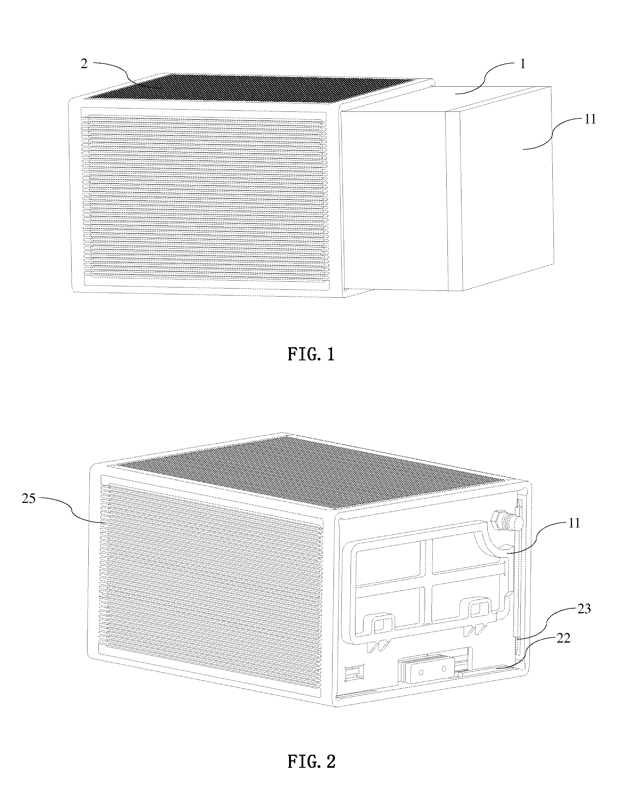
[0023]With reference to FIG. 1, the present invention provides a battery pack injected with a phase change material, comprising a plurality of battery modules 1 and a pack case 2, the battery modules 1 comprises of a plurality of stacked battery cells, and the battery modules 1 are held in the pack case 2. The barrel pack case 2 may be formed by four aluminum plates.

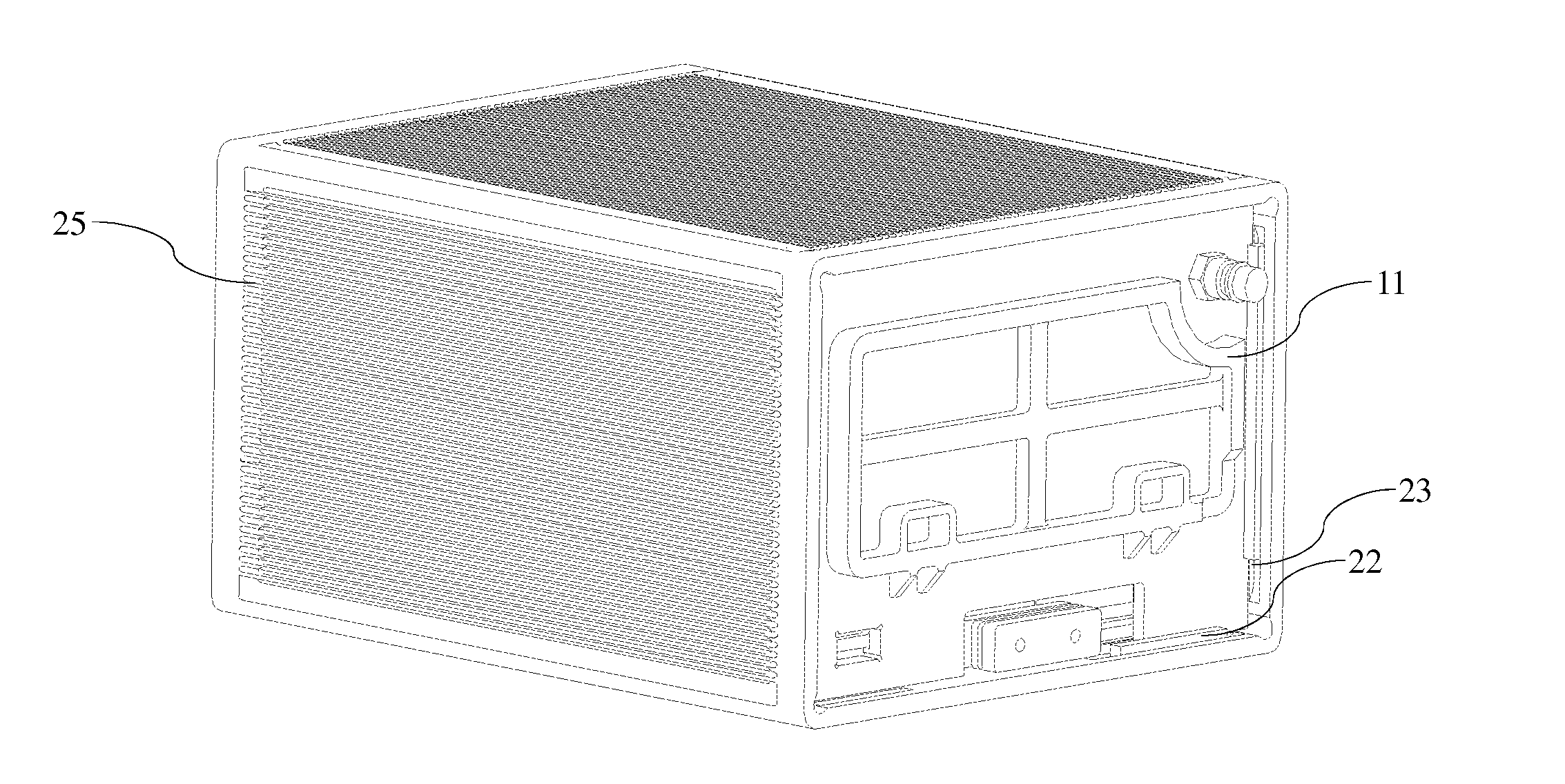
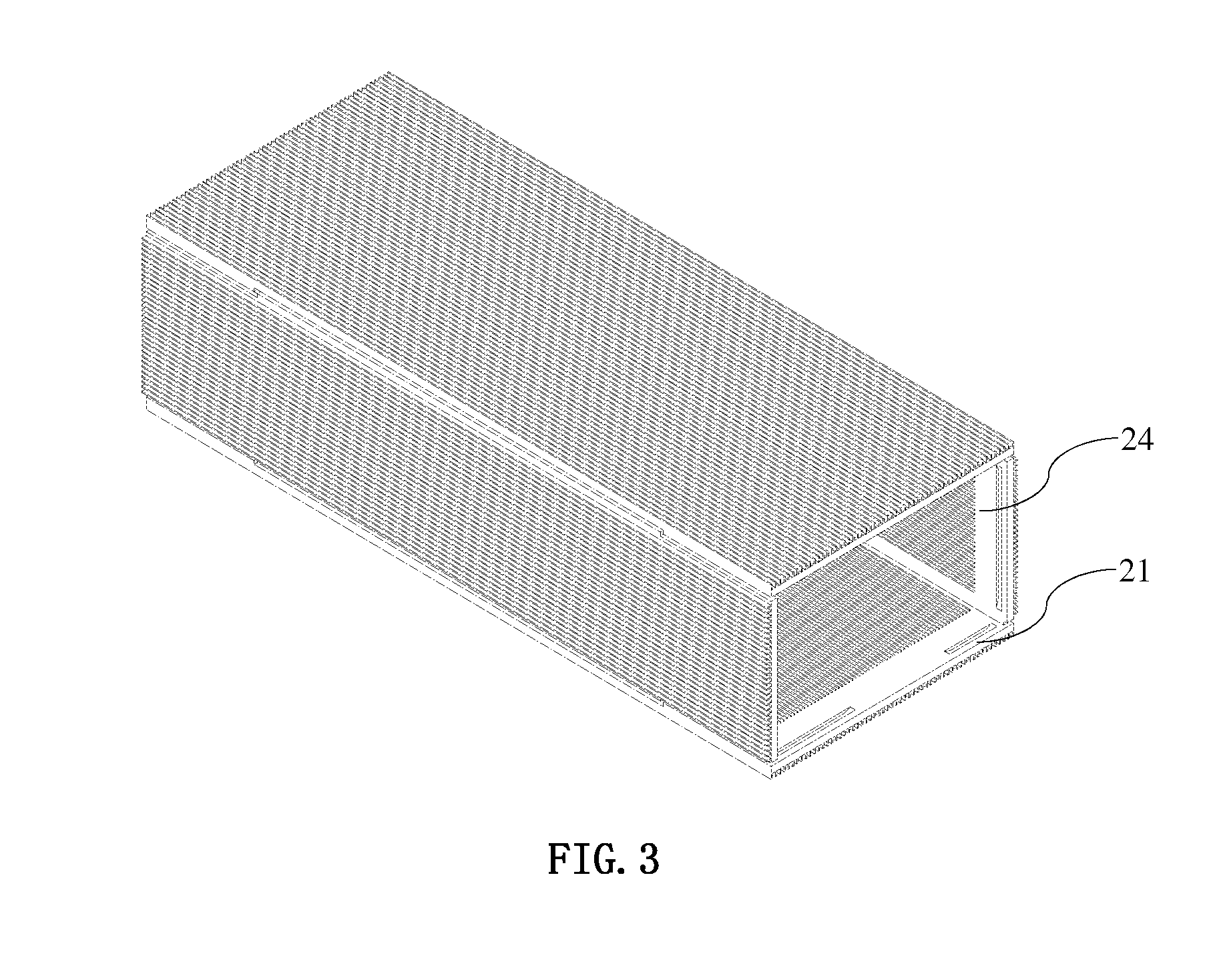
[0024]With reference to FIG. 2 and FIG. 3, mounting grooves 21 are formed or built in the four aluminum plates of the pack case 2 and adjacent to the open ends of the four aluminum plates. Coupled stoppers 22 are installed in the mounting grooves 21. Endplates 11 are installed on both sides of the battery modules 1. The endplates 11 are fixed by the combination of the mounting grooves 21 and the stoppers 22, and thus the battery modules 1 cannot stretch out of the pack case 2. A thermal conductive layer 24 is built on the internal surface of the pack case 2. The thermal conductive layer 24 may be a rough metal coating.

[0...

example 2

[0027]With reference to FIG. 1, the present invention provides a battery pack injected with phase change material, comprising a plurality of battery modules 1 and a pack case 2. The battery modules 1 has a plurality of stacked battery cells. The battery modules 1 are held in the pack case 2. The pack case 2 is formed by four aluminum plates.

[0028]With reference to FIG. 2 and FIG. 3, mounting grooves 21 are installed in the four aluminum plates of the pack case 2 and adjacent to the open ends of the four aluminum plates. Coupled stoppers 22 are provided in the mounting grooves 21. The endplates 11 are built on both sides of the battery modules 1. The endplates 11 are stabilized or fixed by the combination of the mounting grooves 21 and the stoppers 22, so that the battery modules 1 cannot stretch out of the pack case 2. A thermal conductive layer 24 is placed on the internal surface of the pack case 2. The thermal conductive layer 24 is rough metal coating.

[0029]The spring interlayer...

example 3

[0031]With reference to FIG. 1, the present invention provides a battery pack injected with phase change material, comprising a plurality of battery modules 1 and a pack case 2. The battery modules 1 has a plurality of stacked battery cells, and the battery modules 1 are held in the pack case 2. The pack case 2 is formed by four aluminum plates.

[0032]With reference to FIG. 2 and FIG. 3, the mounting grooves 21 are built in the four aluminum plates of the pack case 2 and adjacent to the open ends of the four aluminum plates. The coupled stoppers 22 are installed in the mounting grooves 21. The endplates 11 are installed on both sides of the battery modules 1. The endplates 11 are fixed by the combination of the mounting grooves 21 and the stoppers 22, so that the battery modules 1 cannot stretch out of the pack case 2. A thermal conductive layer 24 is built on the internal surface of the pack case 2. The thermal conductive layer 24 is a rough metal coating.

[0033]The spring interlayer...


PUM

PropertyMeasurementUnit
pressureaaaaaaaaaa
pressureaaaaaaaaaa
pressureaaaaaaaaaa

Abstract

The present invention provides a battery pack injected with phase change material, comprising a plurality of battery modules consisting of a plurality of stacked battery cells and a pack case housing the battery modules. The battery pack is hermetic, and injected with hydrofluoroether. The pressure in the pack case is between −0.09 MPa and −0.01 MPa.

Description

[0001]This application claims priority as per Paris Convention based upon the Chinese patent Filed on Sep. 24, 2013 with the Chinese patent office having application number 201310438765.9, the content of which is hereby incorporated herein by references in entirely.FIELD OF THE INVENTION [0002]The present invention relates generally a battery pack system, more specifically the present invention relates to a battery pack injected with phase change material.BACKGROUND [0003]As the global energy crisis and environment pollution become more and more serious, a new solution must be adopted in the development of the automobile industry. Electric vehicles are gradually attracting public attention due to its advantage of higher voltage, higher specific energy, better cycling performance and pollution free feature. Further, electric vehicles considered as the most promising automotive vehicles.[0004]However, the lithium ion batteries of an electric vehicle need to operate in a certain temper...

Claims


Application Information

Patent Timeline
Patent Type & Authority Applications(United States)
IPC IPC(8): H01M10/659H01M10/6551H01M50/204H01M50/224H01M50/244
CPCH01M10/5046H01M10/5089H01M2220/20H01M10/0481H01M50/244H01M50/224H01M50/204H01M10/6551H01M10/6554H01M10/659Y02E60/10Y02P70/50
Inventor YANG, CONGMING
Owner MICROVAST
Why Eureka
Try Eureka