Vibration testing device

Inactive Publication Date: 2015-04-02
LEE KUN TA
View PDF6 Cites 3 Cited by
  • Summary
  • Abstract
  • Description
  • Claims
  • Application Information

AI Technical Summary

Benefits of technology

The present invention relates to a vibration testing device with a water cooling system. The device is designed to reduce the operating temperature and power consumption of the vibration assembly. It includes a platform, a vibration assembly, a housing, and a water cooling system. The fan at the outside of the housing generates airflow through the inlet, vibration assembly, and outlet, while the atomizing assembly at the inlet generates atomized water to absorb waste heat generated by the vibration assembly. This results in reducing the working temperature of the vibration assembly and power consumption of the device.

Problems solved by technology

Various products that are used in everyday lives may be subjected to random vibrations or disturbances, e.g., vibrations generated by the movement of vehicles, disturbances generated by airplanes in airflow, or random vibrations generated during the handling process of machines.
When the products are exposed to such vibrations for a long period of time, predetermined functions of the products may be negatively affected if no appropriate design is made.
The simulated vibration test requires long-time repeated actions, so if the generated waste heat cannot be removed effectively during the simulated vibration test, the material temperature will rise and degrade the material strength.
Furthermore, the original characteristics of the high-permeability materials will degrade under high temperatures.
In addition, normal operations of the vibration assembly 120 will be severely compromised, which will adversely affect the accuracy of the simulated vibration test and shorten the service life of the vibration testing device 100.
That is, when the resistance is increased because of the increased temperature, copper wires will be severely oxidized to cause increased electrical resistivity, which in turn increases the power consumption of the simulated test to cause dramatic waste of electrical power.

Method used


Image

  • Vibration testing device
  • Vibration testing device
  • Vibration testing device

Examples


Embodiment Construction

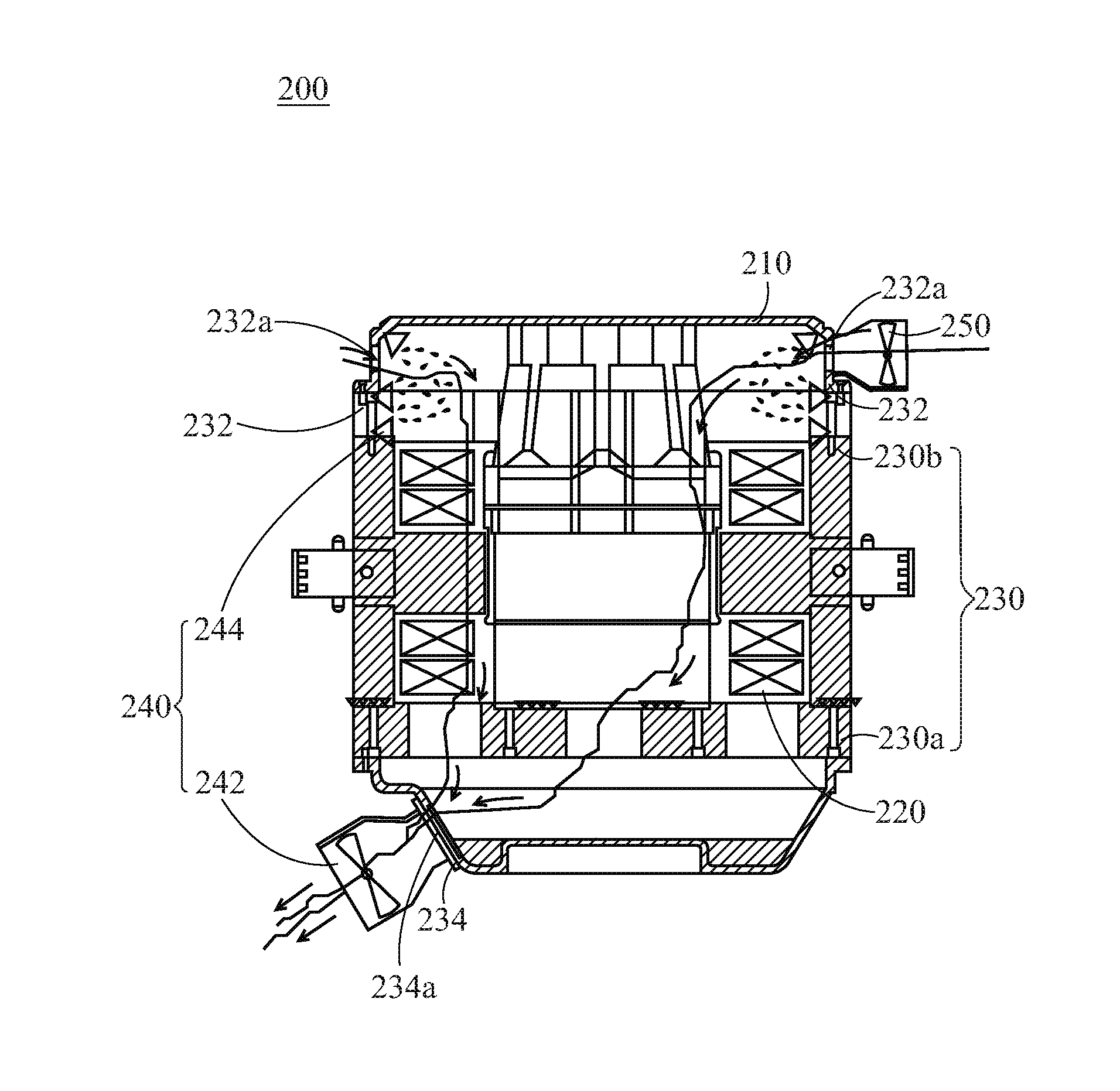
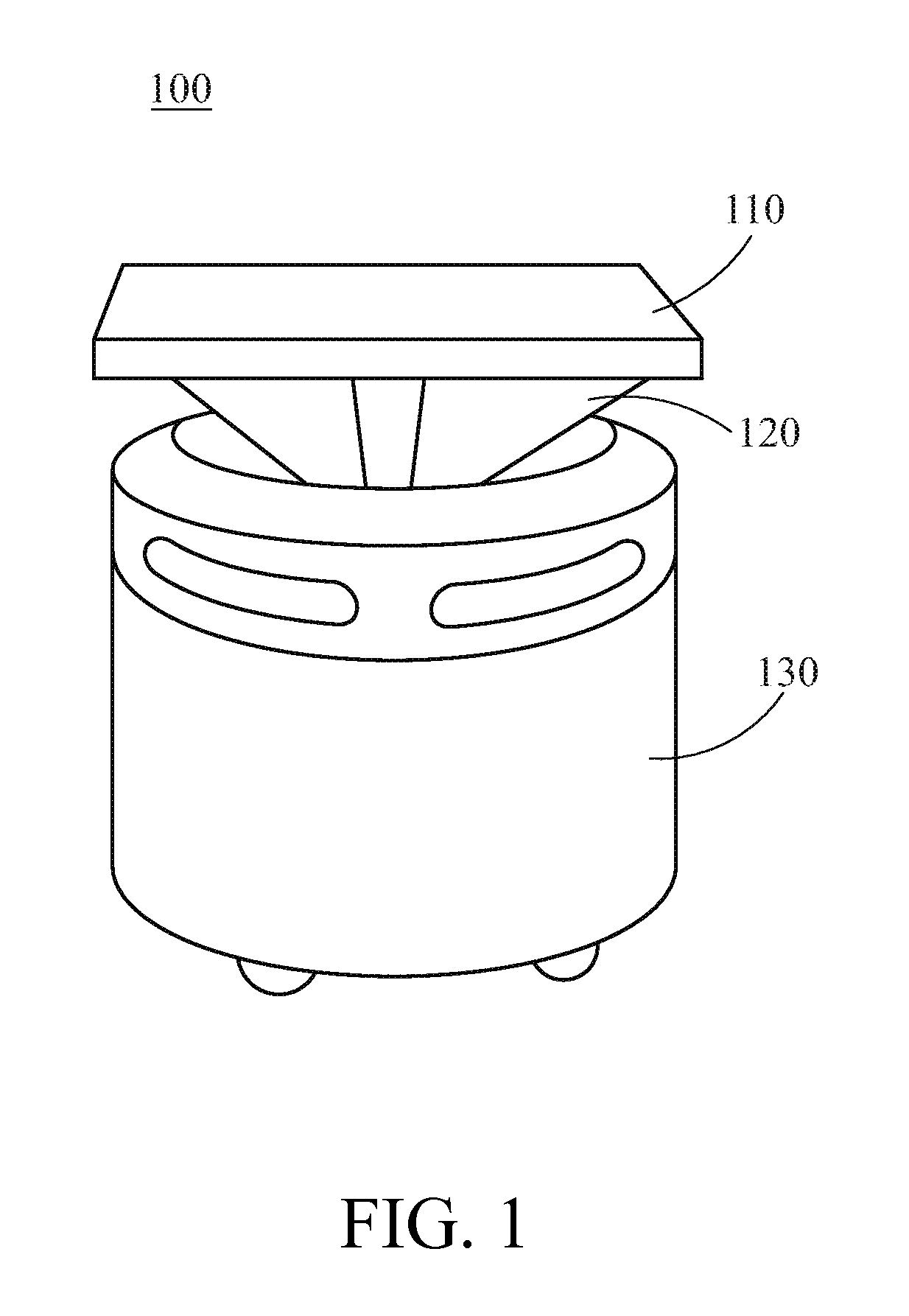
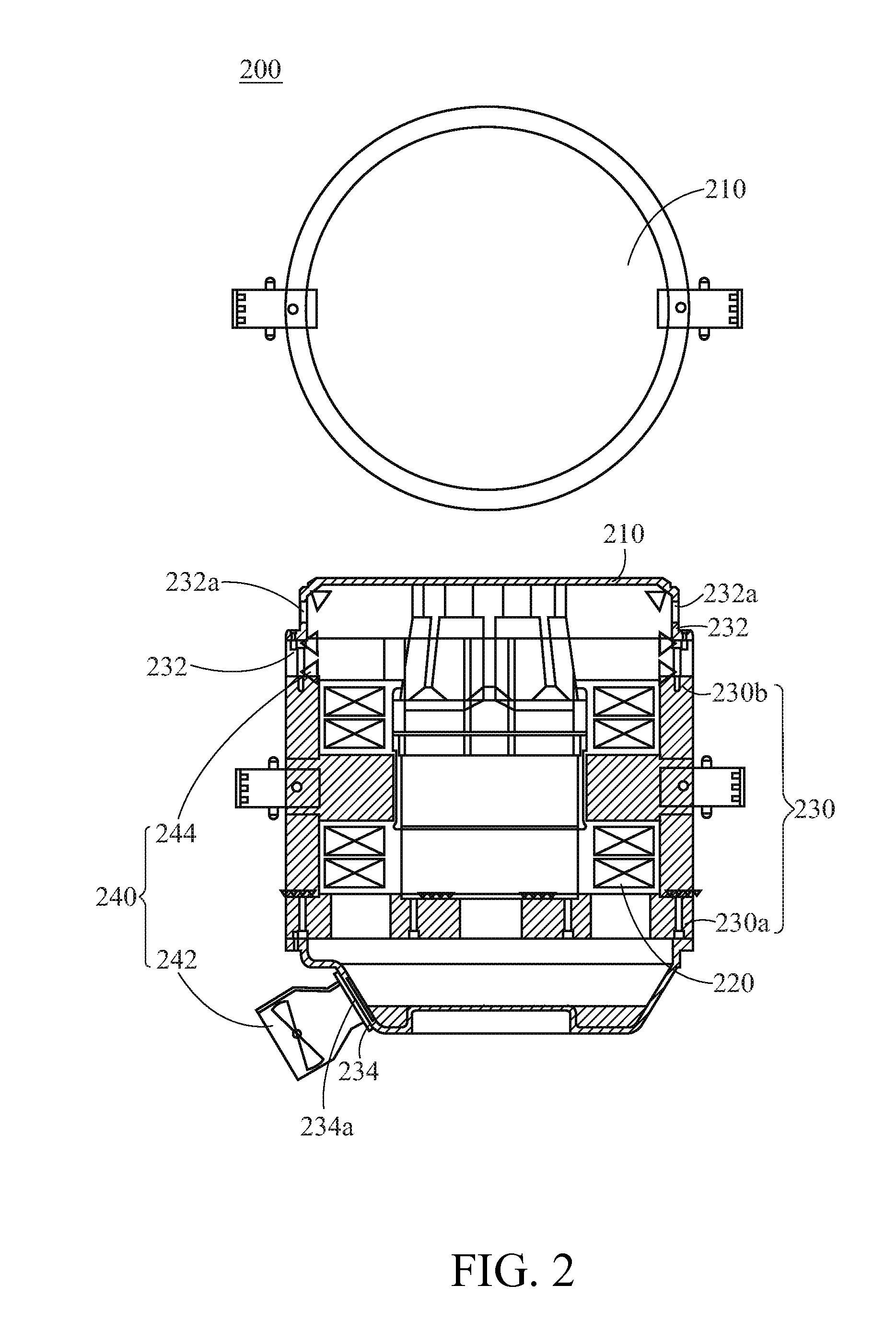
[0026]As shown in FIG. 2, a vibration testing device 200 of the present invention comprises a platform 210, a vibration assembly 220, a housing 230, and a water cooling system 240.

[0027]The platform 210 is utilized for holding a test object (not shown). The vibration assembly 220 is adapted to force a vibration to the platform 210. The housing 230 has an inlet end 232 and an outlet end 234 opposite the inlet end 232. As shown in FIG. 2, the housing 230 is preferably disposed under the platform 210 and is utilized for covering the vibration assembly 220 to isolate the vibration assembly 220 from the external environment so that the vibration assembly 220 is prevented from being subjected to external impact or interference during its operation.

[0028]The water cooling system 240 has a fan 242 and an atomizing assembly 244. The fan 242 is disposed at the outlet end 234 of the housing 230. The atomizing assembly 244 is disposed at the inlet end 232 of the housing 230. With reference to F...


PUM


Abstract

A vibration testing device with a platform, a vibration assembly, a housing and a cooling system is provided. The platform is adapted to hold a test object. The vibration assembly is adapted to force a vibration to the platform. The housing has an inlet end and an outlet end opposite the inlet end. The housing is disposed under the platform and covers the vibration assembly. The cooling system with a fan and an atomizing assembly, and is disposed on the housing. The fan is adapted to generate an airflow. The atomizing assembly is adapted to generate atomized water. The airflow with the atomized water passes through the inlet end, the interior of the housing and the outlet end sequentially to reduce the working temperature of the vibration assembly.

Description

[0001]This application claims the benefit from the priority to Taiwan Patent Application No. 102218468 filed on Oct. 2, 2013, the disclosures of which are incorporated by reference herein in their entirety.CROSS-REFERENCES TO RELATED APPLICATIONS[0002]Not applicable.BACKGROUND OF THE INVENTION[0003]1. Field of the Invention[0004]The present invention relates to a vibration testing device; and more particularly, the present invention relates to a vibration testing device comprising a water cooling system.[0005]2. Descriptions of the Related Art[0006]Various products that are used in everyday lives may be subjected to random vibrations or disturbances, e.g., vibrations generated by the movement of vehicles, disturbances generated by airplanes in airflow, or random vibrations generated during the handling process of machines. When the products are exposed to such vibrations for a long period of time, predetermined functions of the products may be negatively affected if no appropriate d...

Claims


Application Information

Patent Timeline
IPC IPC(8): G01N29/32G01N29/34
CPCG01N29/326G01N2291/028G01N29/34G01M7/022G01M7/02
Inventor LEE, KUN-TA
Owner LEE KUN TA
Why Eureka
Try Eureka