Image processing apparatus and image processing method

Active Publication Date: 2015-04-02
CANON KK
View PDF6 Cites 7 Cited by
  • Summary
  • Abstract
  • Description
  • Claims
  • Application Information

AI Technical Summary

Benefits of technology

[0008]The present invention is made in order to solve the above-described problem. Therefore, an object of the present invention is to provide a quantization pro

Problems solved by technology

However, even in the case of employing the quantization process enabling high dispersibility, mutually superimposing multicolor dots on a sheet of paper like color image printing may deteriorate graininess.
On the other hand, in the case of performing a quantization process for each of the colors in an independent and uncorre

Method used


Image

  • Image processing apparatus and image processing method
  • Image processing apparatus and image processing method
  • Image processing apparatus and image processing method

Examples


Example

First Embodiment

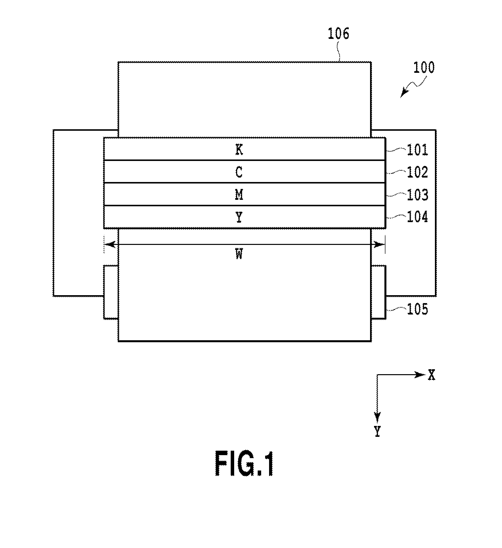
[0027]FIG. 1 is a top view of a printing unit of a full-line type inkjet printing apparatus (image forming apparatus) applicable to the present embodiment. In the inkjet printing apparatus 100, print heads 101 to 104 are fixedly equipped on a frame as illustrated in the view. In each of the print heads 101 to 104, multiple printing elements ejecting a corresponding single color of black (K), cyan (C), magenta (M), and yellow (Y) inks are arrayed at regular pitches in an X direction in the view correspondingly to the width W of a print medium 106. The print medium 106 is conveyed at a constant rate in a Y direction as a conveyance roller 105 is rotated by an unillustrated motor as a driving source. In the course of the conveyance, each of the printing elements ejects a corresponding color of the inks according to print data to thereby print a predetermined image on the print medium 106.

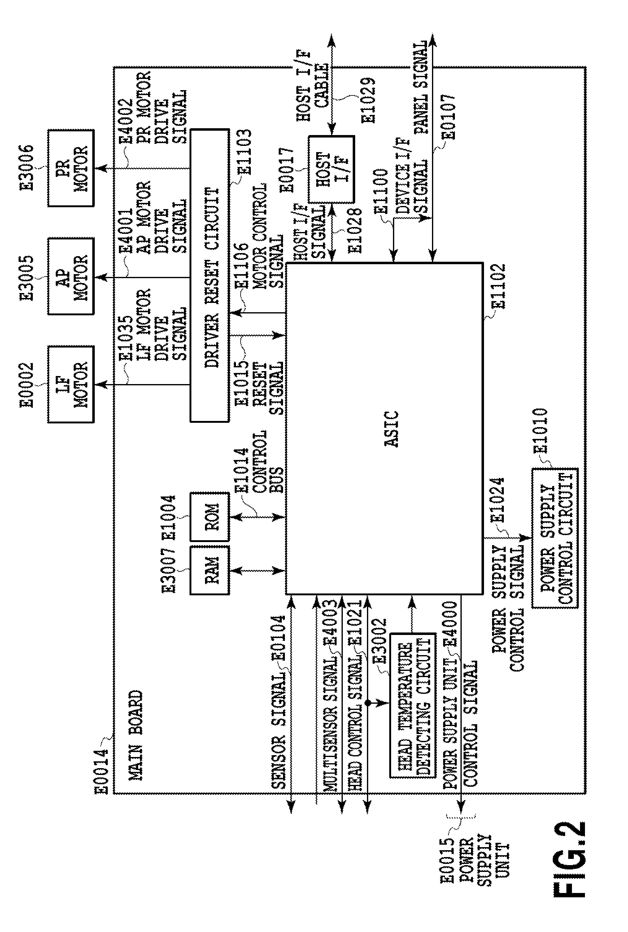
[0028]FIG. 2 is a block diagram illustrating an internal configuration of a printer...

Example

Second Embodiment

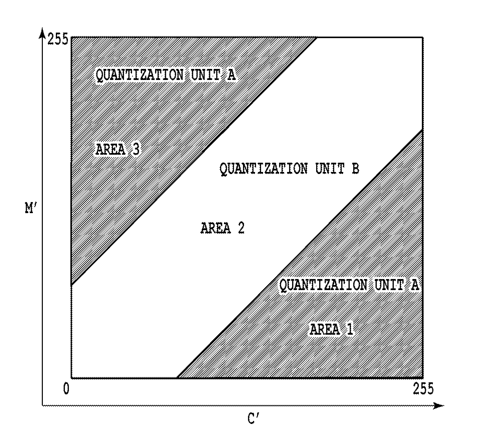
[0054]FIG. 6 is a main part block diagram for explaining image processing performed by an ASIC E1102 in the present embodiment. A point of difference from the first embodiment illustrated in FIG. 3 is that a dot generation history detecting unit 601 is prepared. In the present embodiment, the dot distribution estimating unit 312 selects one of the set of quantization units A and the set of quantization units B on the basis of, in addition to the output value C′ from the cyan gradation correcting process 302 and the output value M′ from the magenta gradation correcting process 303, an output value from the dot generation history detecting unit 601, as well.

[0055]Inkjet printing used in the present embodiment is configured to apply a voltage pulse to a heater equipped for each printing element according to a print signal. Also, the inkjet printing is configured to generate film boiling in ink in contact with the heater, and eject the ink as a droplet by growth energy ...

Example

Third Embodiment

[0062]FIG. 8 is a main part block diagram for explaining image processing performed by an ASIC E1102 in the present embodiment. A point of difference from the second embodiment illustrated in FIG. 6 is that in place of the dot generation history detecting unit 601, a temperature detecting unit 801 is prepared. The temperature detecting unit 801 detects current temperatures of the print heads 102 and 103, and outputs values of the temperatures to the dot distribution estimating unit 312. Then, the dot distribution estimating unit 312 selects any one of the set of quantization units A and the set of quantization units B on the basis of, in addition to the output value C′ from the cyan gradation correcting process 302 and the output value M′ from the magenta gradation correcting process 303, the temperature detected values from the temperature detecting unit 801, as well.

[0063]In the present embodiment, as well, the tables illustrated in FIGS. 7A and 7B can be used. For...


PUM


Abstract

Provided is a quantization processing method using dither patterns that make it possible to obtain a dot array having excellent dispersibility even in the case of a single color or mixed color inks. For this purpose, first and second dither patterns are prepared in order to respectively quantize multivalued data for a first ink to different pieces of binary data, respectively. Also, third and fourth dither patterns are prepared in order to respectively quantize multivalued data for a second ink to different pieces of binary data. Further, on the basis of a combination of the multivalued data on the first ink and the multivalued data on the second ink, a quantization unit for the first ink, and a quantization unit for the second ink are determined.

Description

BACKGROUND OF THE INVENTION[0001]1. Field of the Invention[0002]The present invention relates to a pseudo halftone process adapted to represent a multi-gradation image with two gradations. In particular, the present invention relates to a quantization process based on a prepared dither pattern.[0003]2. Description of the Related Art[0004]A pseudo halftone process adapted to represent a multi-gradation image with two gradations, i.e., printing (1) and non-printing (2) of a dot, requires a quantization process during converting multivalued density data to binary data. Typical quantization processing methods include an error diffusion method and a dither method, and in particular, the dither method is advantageously used for high-speed printers requiring speed and multicolor printers using a large data quantity in terms of being performable at high speed with less processing load.[0005]A dot array on a print medium is determined by such a quantization process, and in particular, from a...

Claims


Application Information

Patent Timeline
IPC IPC(8): G06K15/02B41J2/21G06K15/10
CPCG06K15/1881G06K15/1878G06K2215/0094B41J2/21G06K2215/101G06K15/102H04N1/4051H04N1/40
Inventor MIYAKE, NOBUTAKANAKAGAWA, JUNICHIYAMADA, AKITOSHIISHIKAWA, TOMOKAZUHORI, SHINJIROGOTO, FUMITAKAIGUCHI, RYOSUKEKAGAWA, HIDETSUGUMURASAWA, KOUTAAKIBA, HIROMITSUSAITO, SENICHI
Owner CANON KK
Why Eureka
Try Eureka