Control circuit and control method for inverter circuit, and control circuit and control method for power conversion circuit

a technology of inverter circuit and control circuit, which is applied in the direction of dc-ac conversion without reversal, process and machine control, instruments, etc., can solve the problems of large system size, increased load of other inverter devices, and reduced reactive power

Active Publication Date: 2015-04-02
DAIHEN CORP
View PDF8 Cites 45 Cited by
  • Summary
  • Abstract
  • Description
  • Claims
  • Application Information

AI Technical Summary

Benefits of technology

[0013]The present invention has been proposed under the abovementioned circumstances. In view thereof, the present invention has as one object to provide a technology that is able to resolve the abovementioned problems.

Problems solved by technology

Also, in the case where a certain inverter device A′ suffers a rise in temperature or has limited remaining capacity, the monitoring device C reduces the reactive power to be compensated by that inverter device A′, and increases the load of the other inverter devices A′.
However, there is a problem with a configuration in which the monitoring device C sets the respective target values for the output reactive power of the inverter devices A′ and the inverter device A″ in that the system becomes large-scale.
There is also a problem in that the system is open to failure due to not readily coping flexibly with an increase or decrease in the number of inverter devices.
Furthermore, there is also a problem in that in the case where the monitoring device C malfunctions, target values can no longer be set.
Note that a similar problem arises even in the case where one of the inverter device A′ (“master”) that has the function of the monitoring device C outputs a target value to the other inverter devices A′ and A″ (“slave”).

Method used


Image

  • Control circuit and control method for inverter circuit, and control circuit and control method for power conversion circuit
  • Control circuit and control method for inverter circuit, and control circuit and control method for power conversion circuit
  • Control circuit and control method for inverter circuit, and control circuit and control method for power conversion circuit

Examples


first embodiment

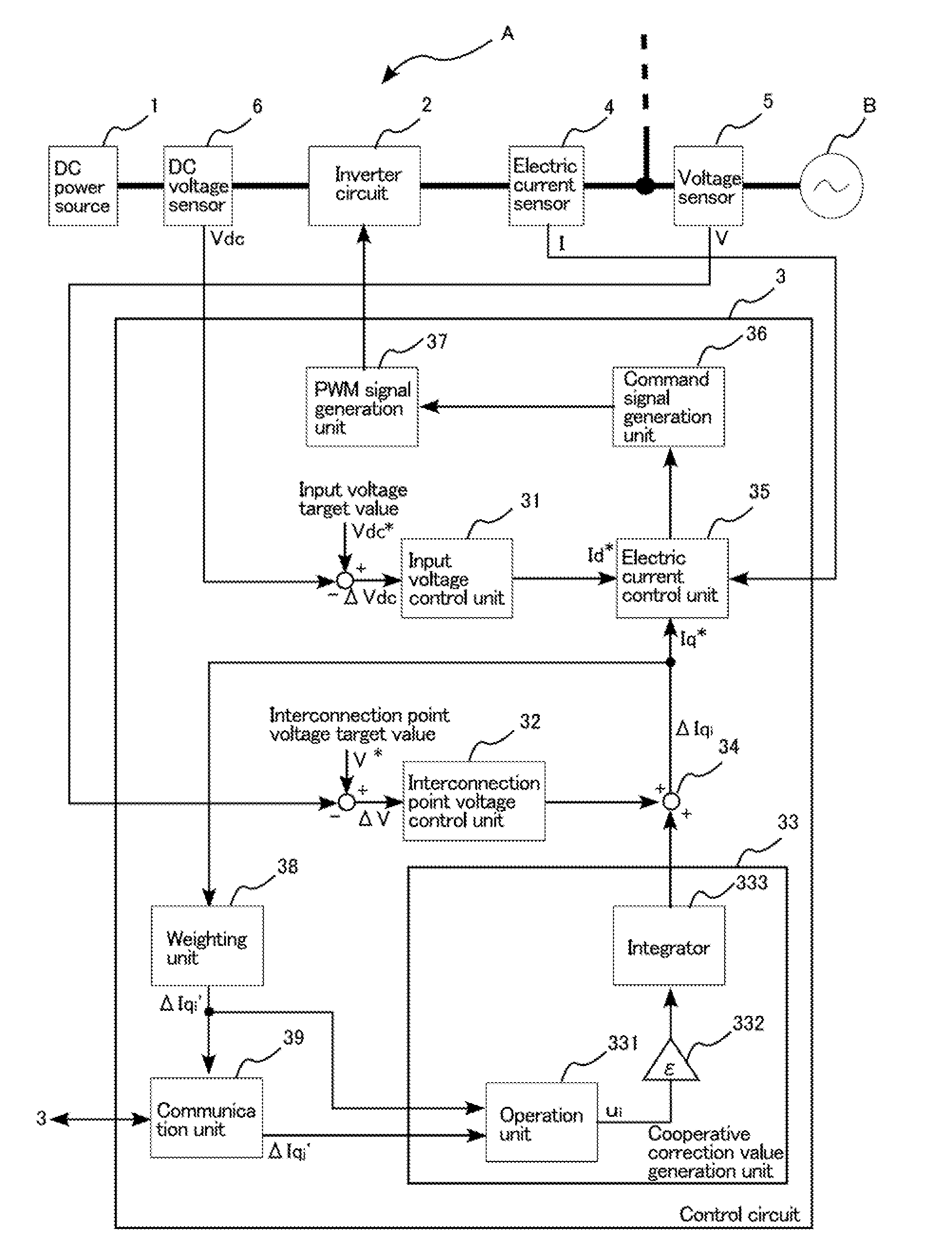
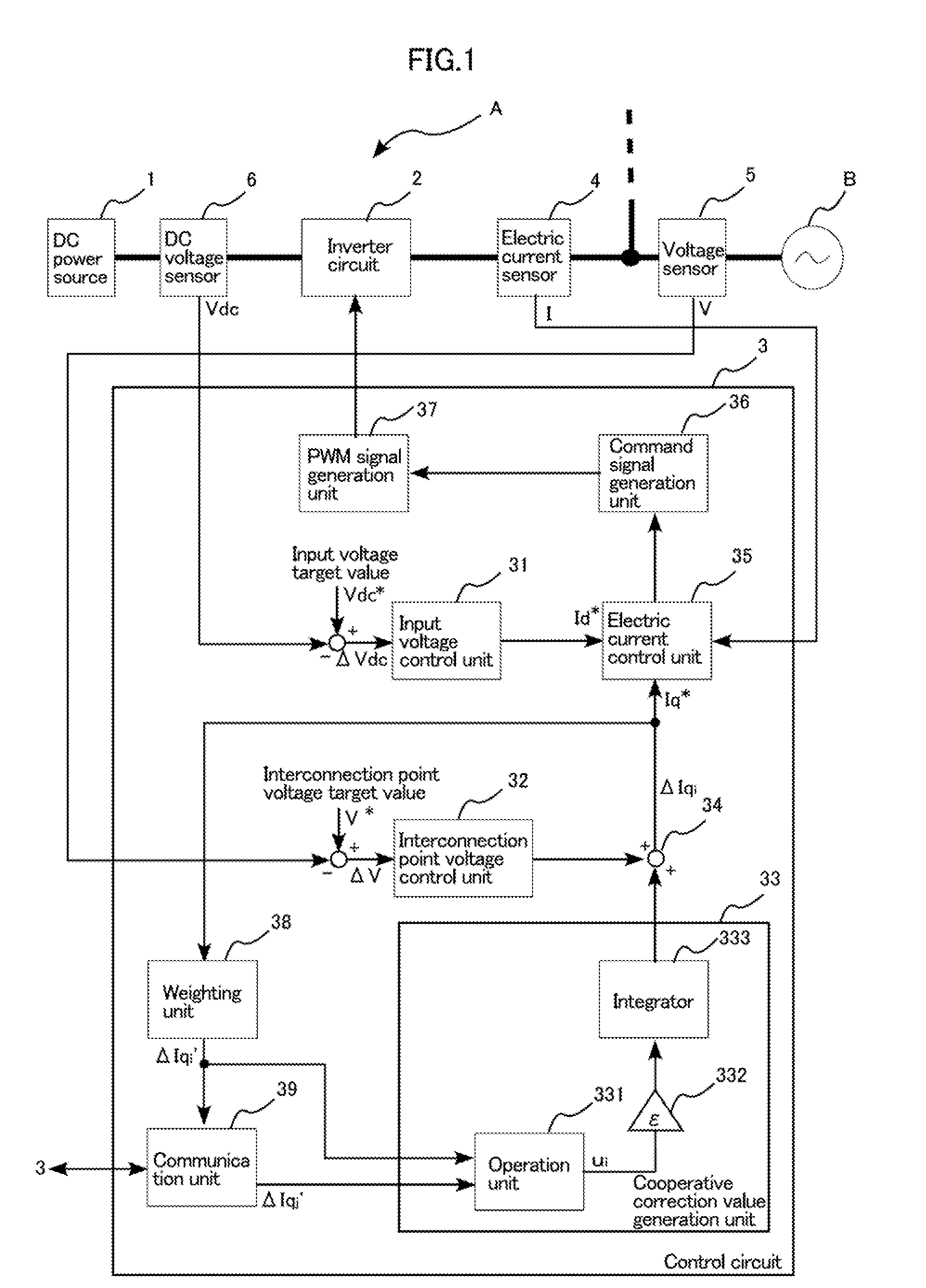
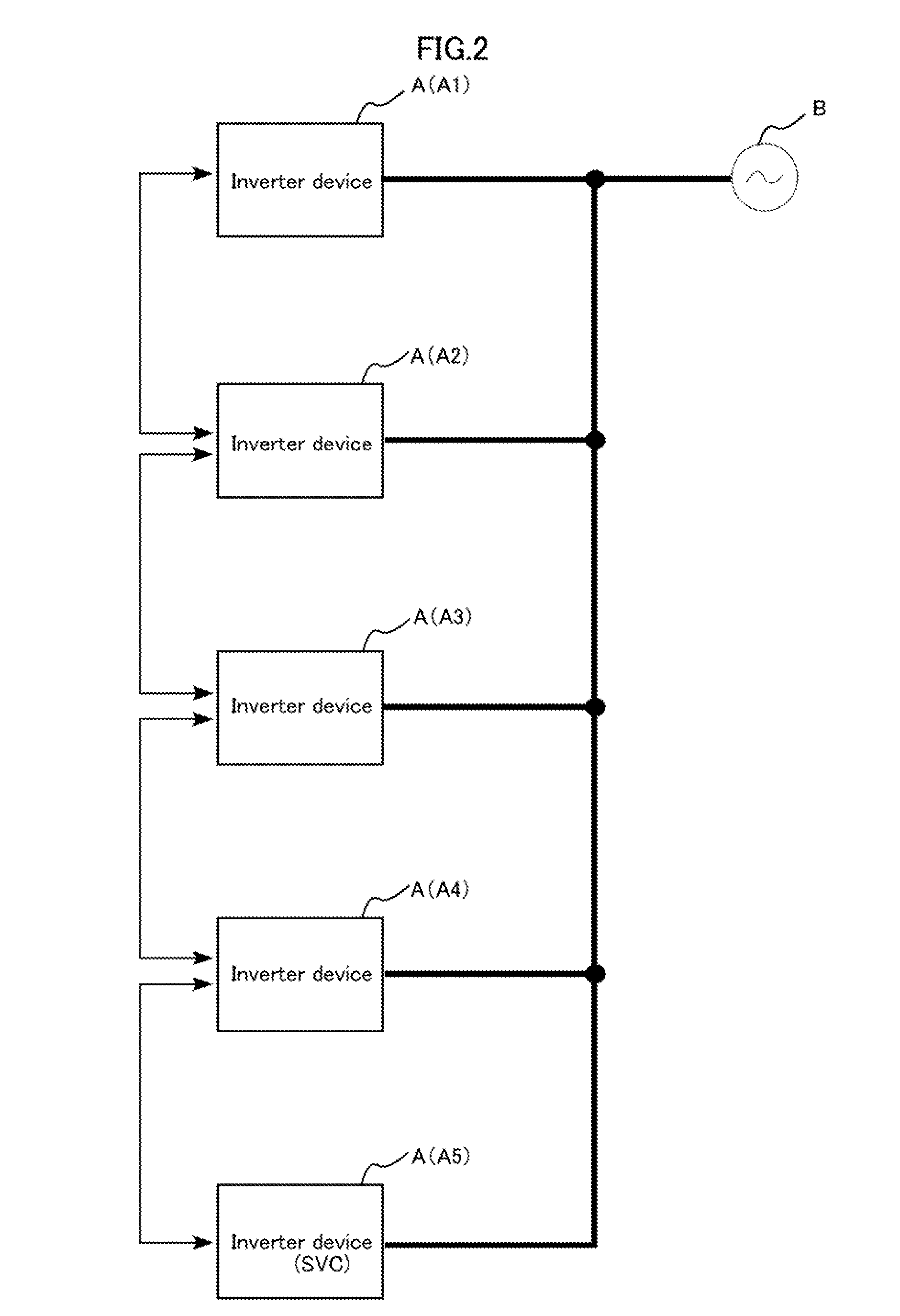
[0162]Note that although the case where the operation equation that is set in the operation unit 331 is the equation (5) was described in the first embodiment, the present invention is not limited thereto. Any other equation that converges the correction values ΔIqi′ of the inverter devices A1 to A5 to the same value may be used.

[0163]For example, the correction values ΔIq1′ can also be converges to the same value in the case where the operation equation that is set in the operation unit 331 is the following equation (7), where di is the number of other inverter devices A with which the communication unit 39 communicates, that is, the number of the correction values ΔIqj′ that is input to the communication unit 39.

ui=1di∑j(ΔIqj′-ΔIqi′)(7)

[0164]The compensation values ΔIqi′ can also be converges to the same value in the case where the operation equation that is set in the operation unit 331 is the following equations (8) to (10).

ui=ΔIqi′∑j(ΔIqj′-ΔIqi′)(8)ui=ΔIqi′2∑j(ΔIqi′-ΔIqj′)(9)ui...

fourth embodiment

[0177]Although the case where the weight value Wi is reduced when the amount of output active power P of the inverter device A is large was described in the fourth embodiment, the present invention is not limited thereto. The weight value Wi may conversely be increased to also increase the output reactive power in response to an increase in output active power P, and the power factors of the inverter devices A may be matched.

Second Aspect

[0178]According to the first aspect of the instant invention, as described above, it becomes possible to control the amount of reactive power that is compensated by each inverter device A′ and A″.

[0179]On the other hand, there is a limit to amount of reactive power that can be compensated. For example, in the case where the capacity of each inverter device A′ and A″ is small or where a minimum power factor is set, reactive power cannot be sufficiently compensated to alleviate a rise in voltage on the power transmission line. In particular, it is dif...

second embodiment

[0425]Also, as in the abovementioned embodiments of the third aspect, each inverter device Ac may communicate with other inverter devices Ac and perform cooperative operation. This case will be described below as the fourth aspect of the instant invention.

[0426]FIG. 47 is for illustrating an inverter device Ac2 according to the second embodiment. In the diagram, the same reference signs are given to elements that are the same as or similar to the inverter device Ac according to the first embodiment (see FIG. 41).

[0427]The inverter device Ac2 according to the second embodiment differs from the inverter device Ac according to the first embodiment in that communication is carried out with other inverter devices Ac2 and an adjustment value is calculated in the control circuit 3c′, instead of receiving input of an adjustment value from the monitoring device Cc. As shown in FIG. 47, the control circuit 3c′ of the inverter device Ac2 according to the second embodiment is further provided w...


PUM


Abstract

A control circuit controls the inverter circuit in one of the non-master-slave inverters connected in parallel in a power system. The control circuit includes: a target parameter controller for generating a compensation value for adjusting a target parameter to the target value; a cooperative correction value generator for generating a correction value for cooperating with another of the inverters; a PWM signal generator for generating a PWM signal based on a correction compensation value obtained by adding the correction value to the compensation value; a weighting unit for weighting the correction compensation value; and a communication unit for communicating with other inverters. The communication unit transmits the weighted correction compensation value to the other inverters. The cooperative correction value generator generates the correction value using an operation result based on the weighted correction compensation value and a reception compensation value received by the communication unit from the other inverters.

Description

BACKGROUND OF THE INVENTION[0001]1. Field of the Invention[0002]The present invention relates to a control circuit and a control method for controlling an inverter circuit, an inverter device provided with the control circuit, and an electric power system provided with the inverter device. Also, the present invention relates to a control circuit and a control method for controlling a power converter circuit, and a power conversion device provided with the control circuit.[0003]2. Description of Related Art[0004]Heretofore, inverter devices that convert direct-current (DC) power that is generated by a solar cell or the like into alternating-current (AC) power and supply the AC power to an electric power grid have been developed. In solar power plants such as mega solar power plants, large amounts of electric power are supplied to the electric power grid by connecting a large number of inverter devices in parallel. Also, a static VAR compensator (SVC) is used in order to alleviate a r...

Claims


Application Information

Patent Timeline
Patent Type & Authority Applications(United States)
IPC IPC(8): H02M7/44H02M1/00H02M1/42H02M7/48H02M7/493H02M7/5387
CPCH02M2001/0003H02M7/44H02M1/42H02M3/04H02M7/53873H02M7/5395H02M7/493H02J2300/10H02J2300/26H02J3/381Y02B70/10Y02E10/56H02M1/0022H02M1/0025H02M1/007H02J3/48H02M1/0043H02M1/0003
Inventor OHORI, AKIHIROHATTORI, NOBUYUKI
Owner DAIHEN CORP
Why Eureka
Try Eureka