Method for spreading a plurality of data symbols onto subcarriers of a carrier signal

Active Publication Date: 2015-04-02
FRAUNHOFER GESELLSCHAFT ZUR FOERDERUNG DER ANGEWANDTEN FORSCHUNG EV
View PDF14 Cites 5 Cited by
  • Summary
  • Abstract
  • Description
  • Claims
  • Application Information

AI Technical Summary

Benefits of technology

[0150]C2: Without loss of data rate and transmission quality, less complex hardware can be utilized for signal processing, or its clock speed can be reduced. In doing so, the costs and/or performance consumption of the system can be reduced.
[0151]For LC spreading, all advantages with respect to the spreading methods known from conventional technology—as is the case for the first aspect, (see advantages A1-A3 above, also compare to simulation results, discussed later) and additionally all advantages, as is the case for the first aspect—result with respect to improved signal statistics (see advantages B1-B3 above, also compare to simulation results, discussed later). In doing so, such signal statistics can be obtained, which can be achieved with all describe

Problems solved by technology

One problem with the transmission via channels with distinct multi-path dispersion (e.g. by means of signals reflected at buildings during radio transmission or reflection onto lines during line-tied transmission) is that destructive interference can cause erasing of subcarriers (“spectral zeros”) in the channel).
Because the symbols modulated onto the affected subcarriers cannot be detected correctly by the receiver, any longer, this causes a high symbol error rate (SER) or a high bit error rate (BER) in the data stream, which only slightly decreases with increasing signal to noise ratio (SNR).
Thus, it cannot readily be compensated for by increasing the transmission capacity.
This involves, however, that it knows the actual radio channel to the receiver (channel state information at transmitter's), which is not the case in many systems.
The reasons for this are, for example, the higher complexity of the system connected therewith, and feedback information that may be used (transmission of channel information from receiver to transmitter), which cause a transmission overhead and have to be made available to transmitter

Method used


Image

  • Method for spreading a plurality of data symbols onto subcarriers of a carrier signal
  • Method for spreading a plurality of data symbols onto subcarriers of a carrier signal
  • Method for spreading a plurality of data symbols onto subcarriers of a carrier signal

Examples


Embodiment Construction

[0163]Embodiments of the invention relate to novel spreading methods (novel spreading matrices and non-matrix-based spreading methods), which are optimized with respect to performance ability, signal statistics, adaptivity and / or efficient implementation.

(First Aspect—Novel Matrix Spreading Methods)

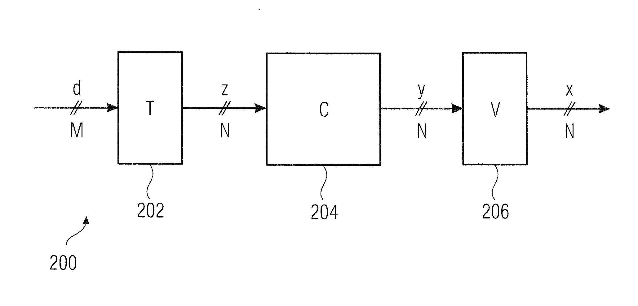
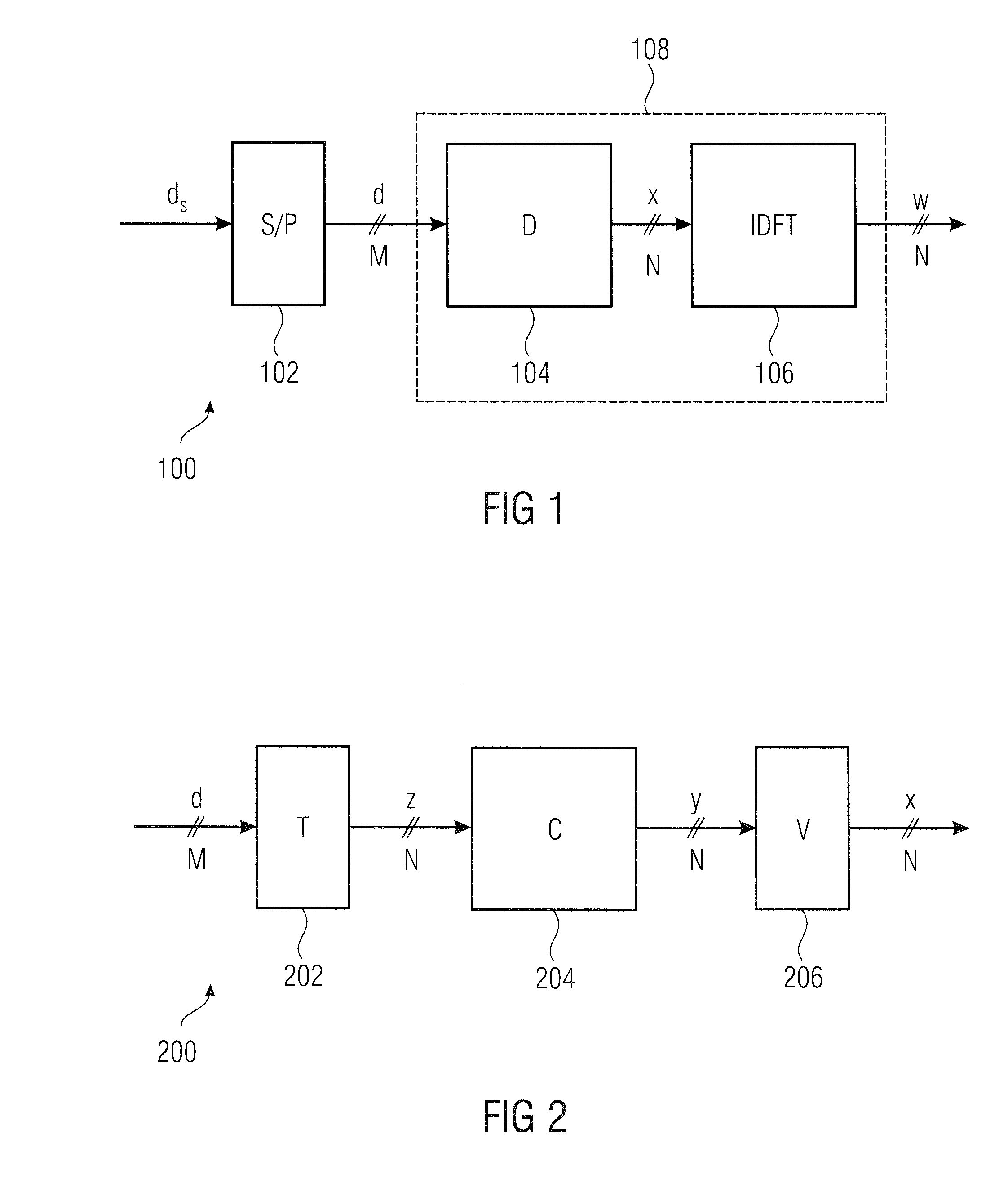
[0164]Embodiments of the invention according to the first aspect relate to novel spreading methods, which have not been considered in conventional technology, yet. The spreading methods are described by means of a spreading matrix, respectively. For further description, the spreading matrix D is split into three matrices T, C and V. We have:

D=VCT.

[0165]T is a matrix of the dimension N×M. It determines “spreading allocation” and will be referred to as “block spreading allocation matrix”, hereafter. C, the “base spreading matrix”, has the dimension N×N (square matrix) and defines “basis spreading”. N will also be referred to as “spreading length, hereafter. V is a diagonal matrix of the di...


PUM


Abstract

A method for spreading a plurality of data symbols onto subcarriers of a carrier signal for a transmission in a transmission system provides a data vector, including the plurality of data symbols. The provided data vector is transformed, and based on the transformed data vector and a spreading matrix subsequent to the transform, a spread data vector is being created, having a length which corresponds to the number of the subcarriers.

Description

CROSS-REFERENCE TO RELATED APPLICATIONS[0001]This application is a continuation of copending International Application No. PCT / EP2013 / 062414, filed Jun. 14, 2013, which is incorporated herein by reference in its entirety, and additionally claims priority from European Application No. 12172212.8, filed Jun. 15, 2012, which is also incorporated herein by reference in their entirety.[0002]The present invention relates to approaches for spreading / de-spreading of a plurality of data symbols onto subcarriers of a carrier signal, particularly novel spreading methods for utilization of frequency diversity in multiple carrier transmission systems.BACKGROUND OF THE INVENTION[0003]The orthogonal frequency-division multiplexing method (OFDM) has established itself in many areas for high-rate data transmission in radio systems with large bandwidth. It is used, for example, in digital audio broadcasting (DAB), digital video broadcasting—terrestrial (DVB-T), in wireless local area networks (WLAN) ...

Claims


Application Information

Patent Timeline
IPC IPC(8): H04L5/00H04L27/26
CPCH04L27/2601H04L5/0044H04B1/69H04L5/0021H04L27/2634H04B1/71632
Inventor KEUSGEN, WILHELMPETER, MICHAELKORTKE, ANDREAS
Owner FRAUNHOFER GESELLSCHAFT ZUR FOERDERUNG DER ANGEWANDTEN FORSCHUNG EV
Why Eureka
Try Eureka