Glass laminate comprising at least one shaped part made of metal

a technology of glass laminate and metal parts, applied in the field of glass laminate, can solve the problems of affecting the quality of glass laminate, and requiring work on openings or cutouts, and achieve the effect of secure and reliable connection, efficient and inexpensive manner

Inactive Publication Date: 2015-04-02
GLAS TROSCH HLDG
View PDF0 Cites 16 Cited by
  • Summary
  • Abstract
  • Description
  • Claims
  • Application Information

AI Technical Summary

Benefits of technology

[0010]It is an object of the invention to provide a glass laminate which is appropriate to the technical field mentioned in the introduction and in the case of which it is possible to introduce a shaped part made of metal, in particular a connection element, in an efficient and inexpensive manner, with a secure and reliable connection being achieved between the shaped part and the laminate.

Problems solved by technology

These methods for fastening connection elements all have the disadvantage that either openings or cutouts have to be worked into one or more of the glass panes of the glass laminate.
Particularly for the production of glass laminates having variable sizes and with different positioning of the connection elements, this represents a not inconsiderable additional outlay which slows down the production of such glass laminates and makes the production more expensive as a whole.
Moreover, when fastening the connection elements via an intermediate polymer layer or a separately applied adhesive, the bond of these connection elements can be ascertained only with difficulty on a permanent basis and can be impaired by external weathering influences, such as solar radiation, moisture or a change in temperature.
Therefore, after a relatively long time the bond between connection element and glass laminate can weaken, and this impairs the operational safety of such a glass laminate.
For structural applications in which it is planned for loads to be removed, this can mean that such an application is not possible.
In addition, cutouts or openings which have been made in the glass panes weaken the glass component as a consequence of increased stresses in the region of the cutouts or openings.

Method used


Image

  • Glass laminate comprising at least one shaped part made of metal
  • Glass laminate comprising at least one shaped part made of metal
  • Glass laminate comprising at least one shaped part made of metal

Examples


Embodiment Construction

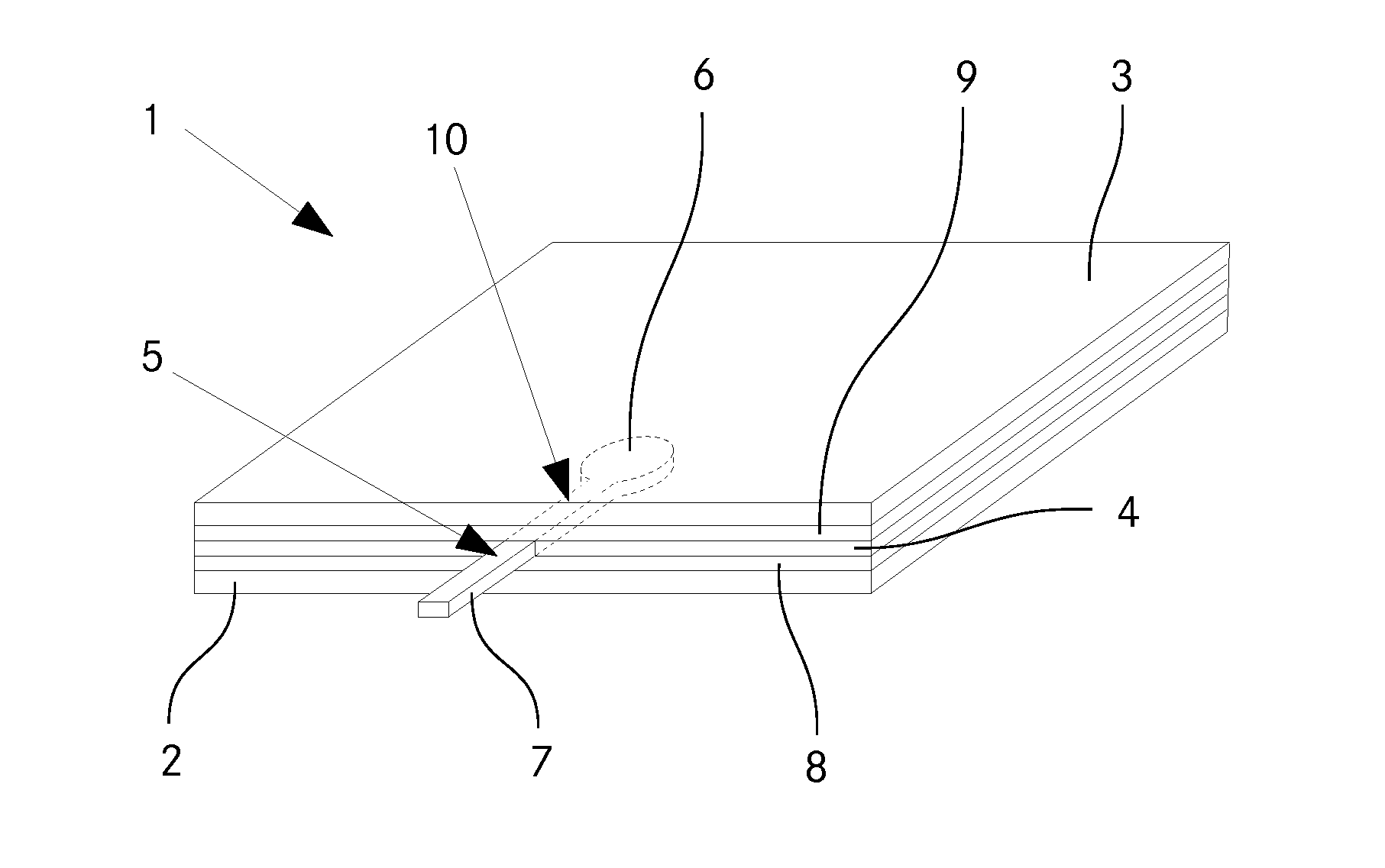
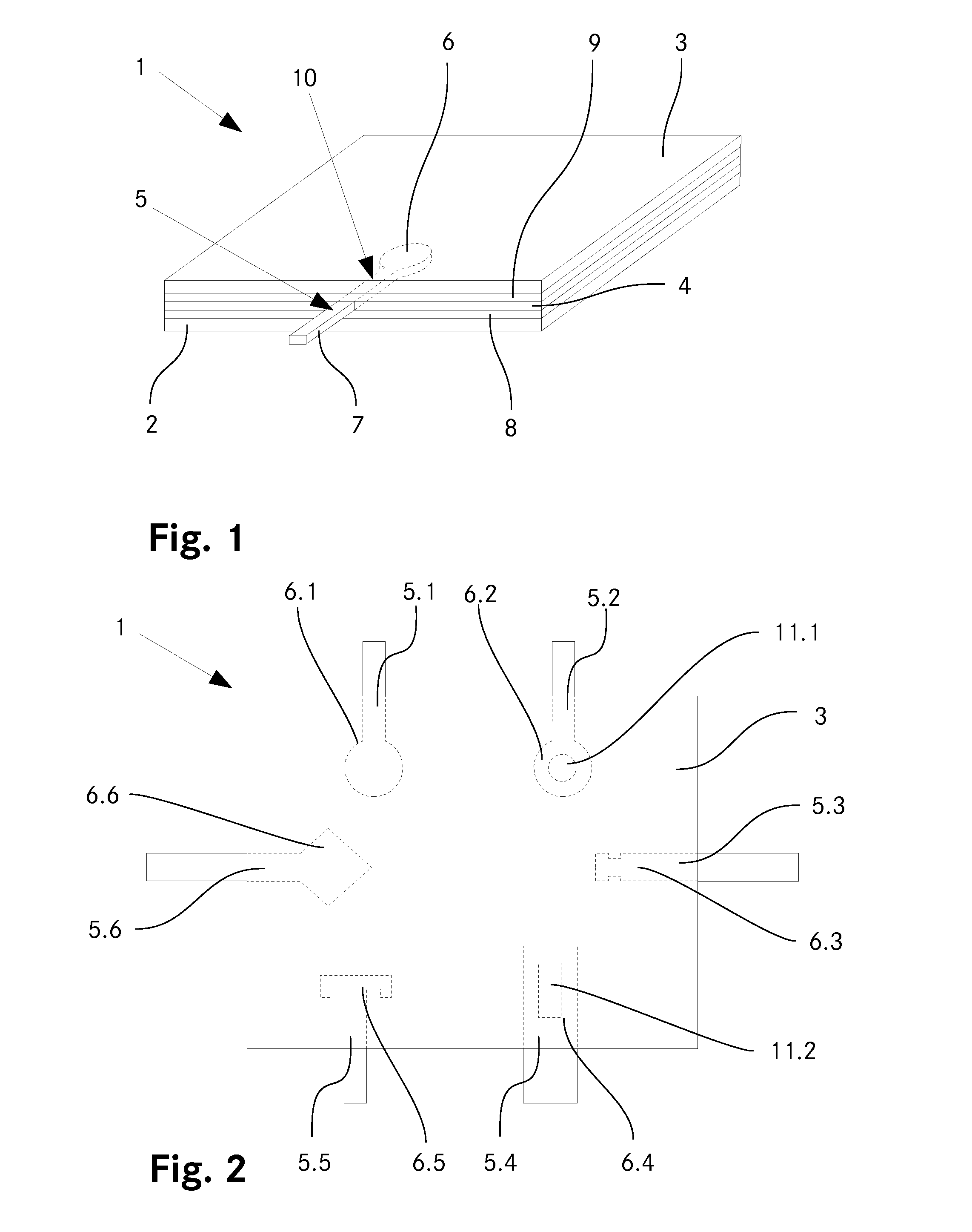
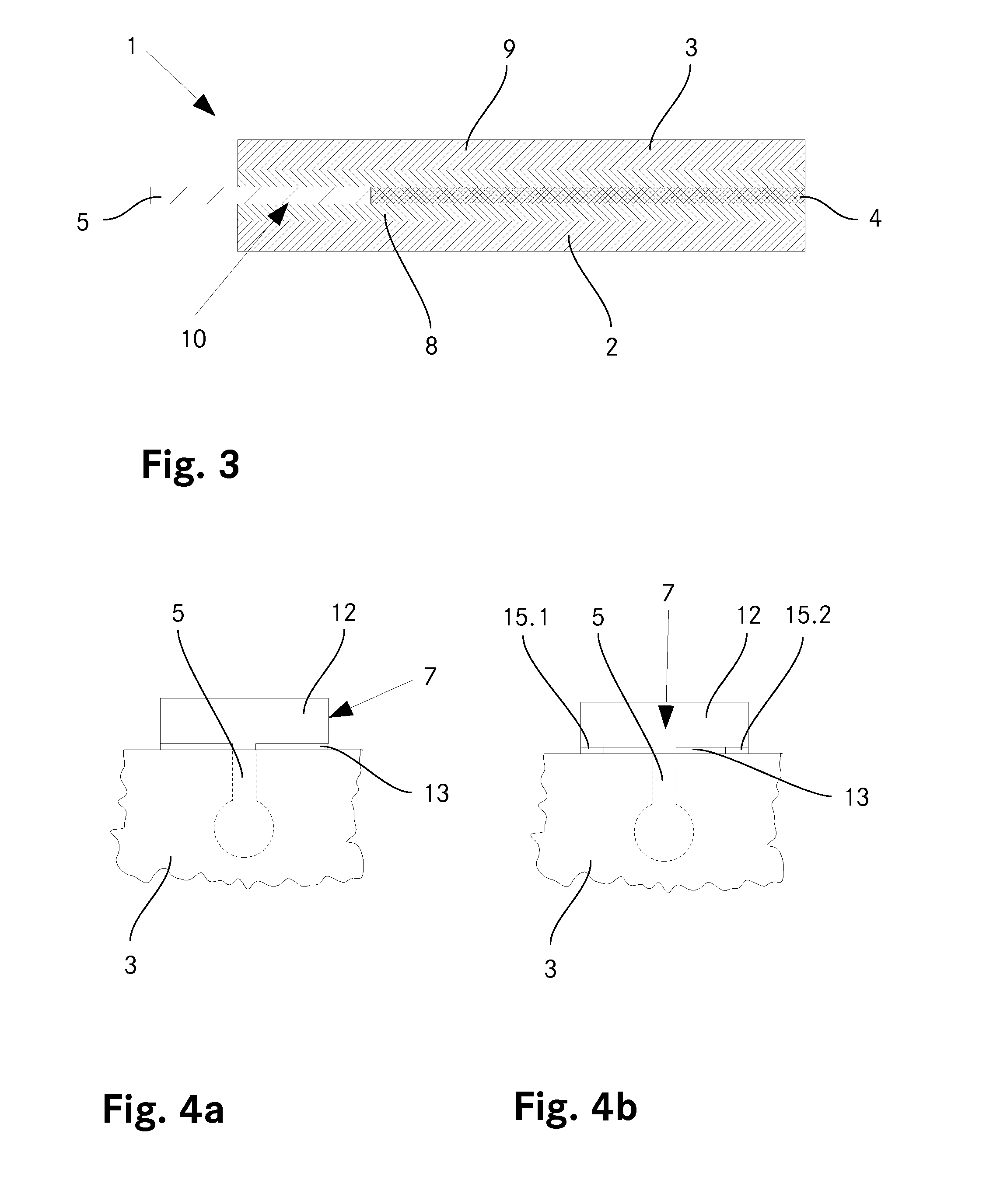
[0056]FIG. 1 shows a glass laminate 1 according to the invention in a perspective view. The glass laminate comprises a first glass plate 2 and also a second glass plate 3. A first polymer film 4 and also two layers of the second polymer film 8, 9 are arranged between the two glass plates 2, 3. In this case, the first polymer film 4 is inserted between the two layers of the second polymer film 8, 9. A second region 7 of a shaped part 5 made of metal protrudes beyond an edge of the glass laminate, whereas a first region 6 of the shaped part 5 is inserted in a cutout 10 in the first film 4. The first region 6 of the shaped part 4 has a shape which engages with the first polymer film 4 in a form-fitting manner in the sense of an undercut. Furthermore, the shaped part 5 is additionally connected to the two glass plates 2, 3 in a force-fitting manner by the layers of the second polymer films 8, 9 which are present between it and the two glass plates 2, 3. Owing to the shape of the second ...


PUM

PropertyMeasurementUnit
temperatureaaaaaaaaaa
thicknessaaaaaaaaaa
widthaaaaaaaaaa

Abstract

The present application relates to a glass laminate (1) comprising at least two glass plates (2, 3). At least one first polymer film (4) and also at least one shaped part (5) made of metal are arranged between said at least two glass plates (2, 3). The at least one shaped part (5) has substantially the same thickness as the at least one first polymer film (4). The first polymer film (4) has a cutout (10), in which there is arranged the shaped part (5). The shaped part (5) furthermore has at least one first region (6) which engages with the at least one first polymer film (4) in a form-fitting manner in the form of an undercut.

Description

TECHNICAL FIELD[0001]The invention relates to a glass laminate comprising at least one polymer film arranged between two glass plates and at least one shaped part made of metal and also to a process for producing such a glass laminate.PRIOR ART[0002]Glass laminates comprising at least one polymer film arranged between two glass plates are known, for example from automotive construction or from the field of safety glasses. Furthermore, various methods for connecting such glasses to further elements, for example a facade, are known in the prior art.[0003]By way of example, U.S. Pat. No. 7,165,362 (Apple Computer) describes a glass laminate as a load-bearing structure, e.g. for a step. A side edge of a glass pane of the laminate has cutouts, into which connection elements can be inserted and in which the latter can be adhesively bonded. The connection elements can be used to fasten the glass laminate structure to further elements. The connection elements can be shaped differently, but ...

Claims


Application Information

Patent Timeline
Patent Type & Authority Applications(United States)
IPC IPC(8): B32B17/10B32B38/00E06B3/66B32B37/18B32B3/08B32B3/06
CPCB32B17/10293B32B3/08B32B3/06B32B17/10036B32B2250/40B32B37/182B32B38/0004B32B2250/03B32B2250/05E06B3/66B32B17/10743E06B3/5436Y10T156/1064Y10T428/24008Y10T428/24777
Inventor KRUGMANN, ROLANDKASSNEL-HENNEBERG, BRUNO
Owner GLAS TROSCH HLDG
Why Eureka
Try Eureka