
Self-pumping liquid and gas cooling system for the cooling of solar cells and heat-generating elements

a solar cell and gas cooling system technology, applied in indirect heat exchangers, lighting and heating apparatus, heat exchangers, etc., can solve problems such as adverse effects, and achieve the effect of high efficiency and low cos

Inactive Publication Date: 2011-07-07
IBM CORP
View PDF17 Cites 14 Cited by
  • Summary
  • Abstract
  • Description
  • Claims
  • Application Information

AI Technical Summary

Benefits of technology

[0006]In order to ameliorate or even possibly entirely eliminate the drawbacks and limitations that are encountered in the prior art, pursuant to the invention there is provided a system which, in a practical manner utilizes heat from the chip, for instance, an element such as a solar cell, in order to drive a pump in a manner analogous to the operation of a steam-driven pump or turbine. In effect, the pump capable of returning coolant to the evaporator from almost any physical orientation able to produce a partial vacuum, and which will draw coolant in an either up or down mode. Moreover, the pump can assist in producing a forcible circulation or coolant throughout the system, while being readily constituted of inexpensive and commercially available structural components. Additionally, the pump presently utilizes a closed circulating system for cooling solar cells that does not require a supply of any external power, inasmuch as the pump is operated or driven itself by any undesired or unwanted waste heat that is generated by the chip or solar cell or array thereof. Hereby the waste heat which tends to normally adversely effect the performance of the solar cell is employed by the system to improve the performance by cooling the chip or solar cell (or array).
[0011]It is another object of the present invention to provide a method utilizing a self-pumping liquid and gas-cooling system for the cooling of heat generating components, such as solar cells in a highly efficient and inexpensive manner.

Problems solved by technology

Hereby the waste heat which tends to normally adversely effect the performance of the solar cell is employed by the system to improve the performance by cooling the chip or solar cell (or array).

Method used


Image

  • Self-pumping liquid and gas cooling system for the cooling of solar cells and heat-generating elements
  • Self-pumping liquid and gas cooling system for the cooling of solar cells and heat-generating elements

Examples


Embodiment Construction

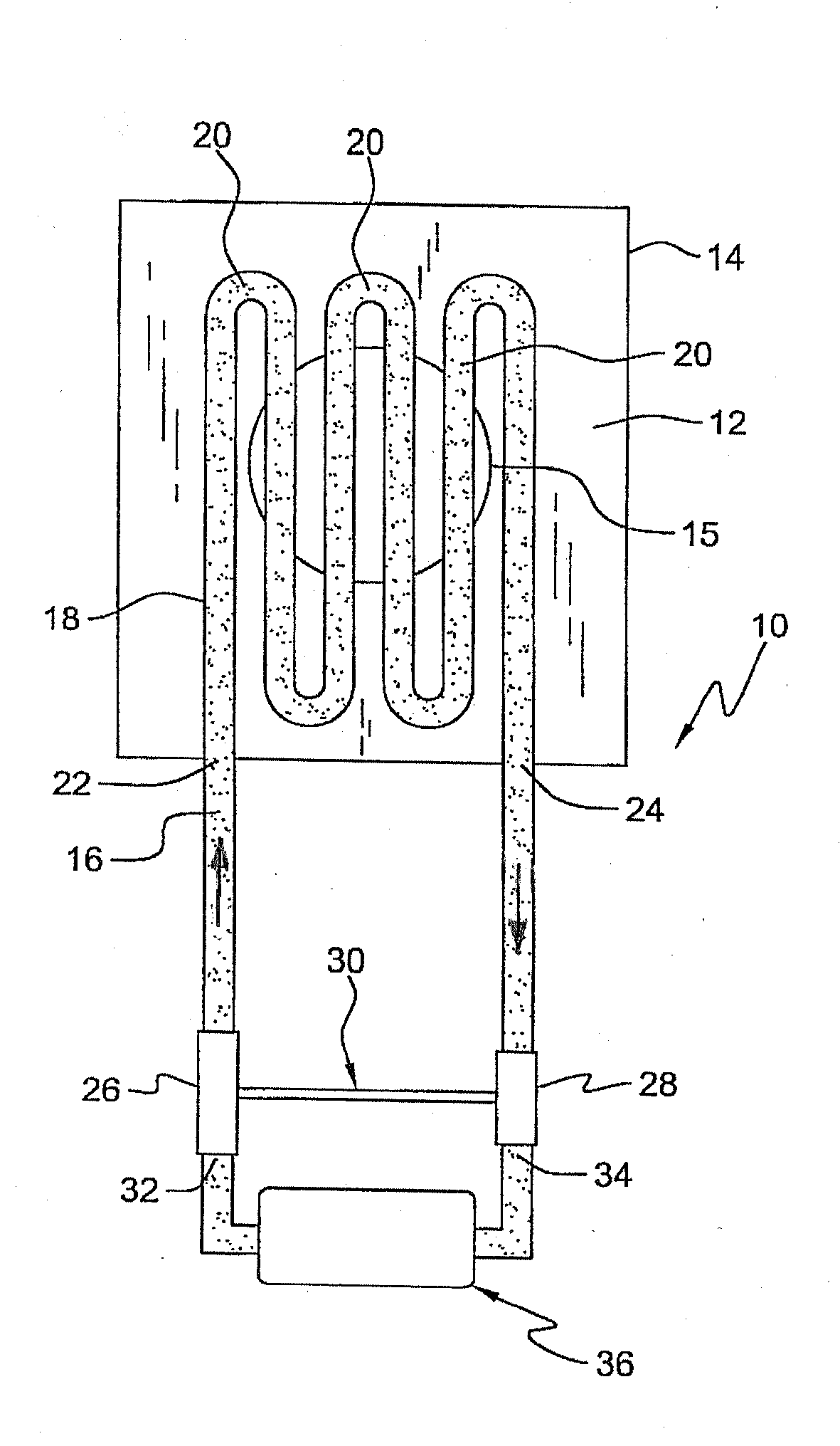
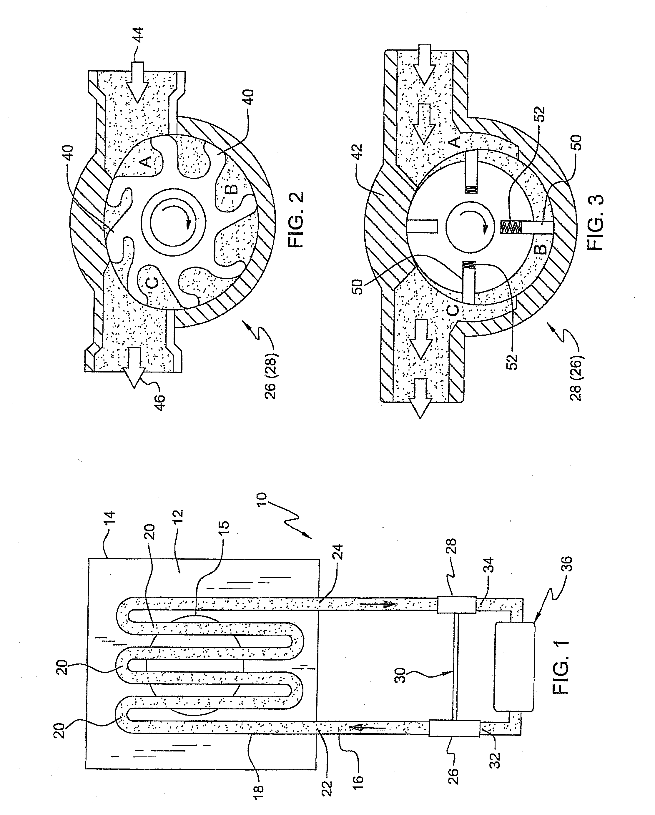
[0016]Referring specifically to the closed coolant system pursuant to the invention, as illustrated in FIG. 1, there is represented a cooling system 10 that includes a heat exchanger which may be constituted of an enclosed housing structure 14 and has a tubing arrangement 18 therein containing or filled with either water or any suitable coolant 16, for example, such as methanol or a coolant solution marketed by 3M Corporation under the designation HFE-7000. In this connection, methanol is particularly suitable when maintained under an operating pressure of about 100 mm Hg. It is also possible to employ ammonia as a coolant, but may be somewhat hazardous to use unless the system is generated remotely from population centers.

[0017]Traversing the heat exchanger 12 is the closed-cycle tubing or piping system 18 of which coils or loops 20 meander therethrough, as illustrated in the drawing. The tubing may be embedded in an array of copper fins, which conduct heat to air, which may includ...


PUM


Abstract

A self-pumping liquid and gas cooling system for the cooling of solar cells and heat generating elements. A method for the self-pumping of liquid and gas coolants utilizes the cooling system. The essentially closed coolant system incorporates a heat exchanger having a length meandering tubing passing therethrough the opposite ends of which are, respectively, in communication with a driving pump and a return pump that are interconnected by a shaft. Hereby, tubing intermediate the circuit formed by the pumps extends through an evaporator structure containing the chip or heat-generating solar cell or cells.

Description

BACKGROUND[0001]The present invention relates to a self-pumping liquid and gas cooling system for the cooling of solar cells and heat generating elements. Moreover, the invention is also directed to the provision of a method for the self-pumping of liquid and gas coolants utilizing a cooling system pursuant to the invention.[0002]Solar cells, as well as other kinds of heat generating components or elements, such as semiconductor chips and electronic devices, inherently process a tendency to generate appreciable amounts of heat, the latter of which must of necessity be designated and removed in an efficient and economical manner, in order to avoid damaging or destroying these heat-generating and other ancillary elements.THE PRIOR ART[0003]At this time, pursuant to the current technology, there are available systems for diverse liquid-gas heat exchanger applications adapted to provide for semi-conductor chip cooling, which utilize thermally pumped liquid and gas flows through siphon c...

Claims


Application Information

Patent Timeline
Patent Type & Authority Applications(United States)
IPC IPC(8): F28D15/00
CPCF28F2250/08F28D15/0266
Inventor MANZER, DENNIS G.
Owner IBM CORP
Learn More