
Systems and methods to determine stiction failures in MEMS devices

a technology of mems devices and stiction failures, applied in the field of integrated micromechanical systems, can solve the problems of short circuit event that destroys the electric field between the two surfaces, stiction adversely affects the device performance, and the mems device of the sensor type is particularly vulnerable to stiction. to achieve the effect of increasing the reliability of the mems devi

Active Publication Date: 2015-04-09
HANKING ELECTRONICS LTD
View PDF13 Cites 19 Cited by
  • Summary
  • Abstract
  • Description
  • Claims
  • Application Information

AI Technical Summary

Benefits of technology

The patent is about a system and method that improves the reliability of MEMS devices by identifying and eliminating units that may suffer from stiction, or may be prone to stiction. This is done through a stress test that uses a high voltage to create a force that causes contact between a movable part and a stationary part in the device. This technology also includes a circuit that allows for the selection between a regular acceleration reading mode and a stiction test mode using the stress test apparatus. Overall, this improves the production of reliable MEMS devices.

Problems solved by technology

Stiction phenomena are well-known problems in MEMS type devices with movable parts.
Sensor type MEMS devices are particularly vulnerable to stiction, which may occur intermittently during regular use of the device or during the manufacturing process.
Stiction adversely affects device performance and may be caused by a variety of forces including capillary forces caused by the presence of moisture and van der Waals forces caused by surface contamination, such as polishing residuals that may fluctuate depending on surface preparation processes.
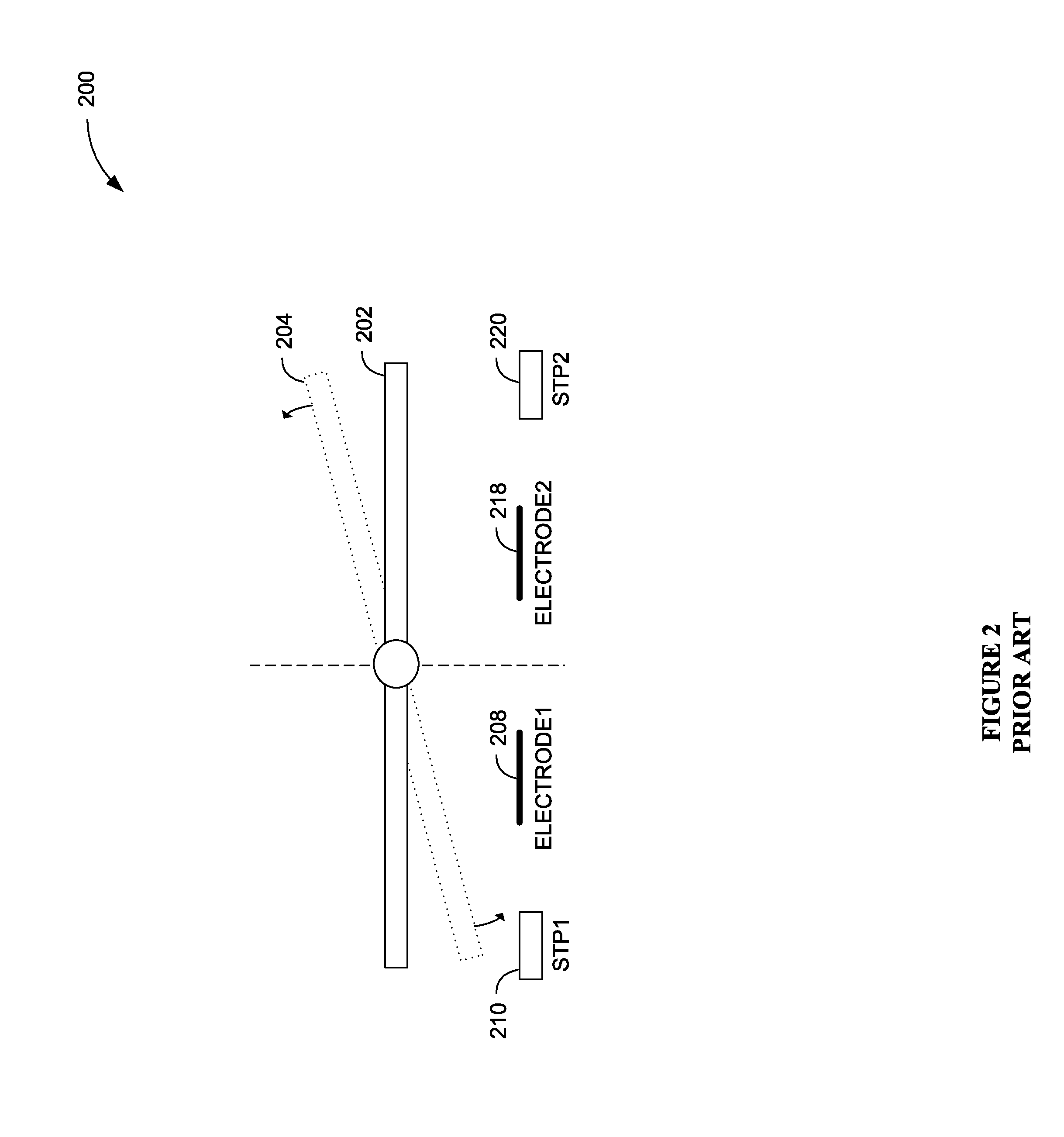
When the total adhesion force between the two surfaces is higher than the mechanical restoring force inherent to the proof-mass, stiction occurs and temporarily immobilizes the proof-mass and prevents it from recovering its original position even after the external disturbance ceases to act on the sensor.
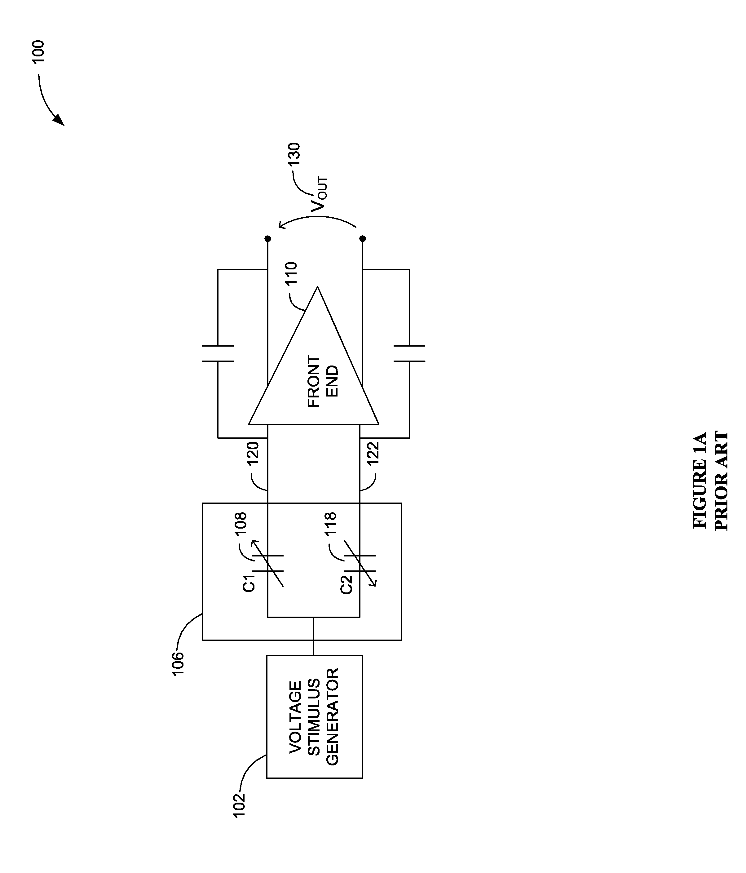
Since stiction causes the proof-mass to adhere to the substrate, the two parts are no longer separated from each other, blocking the movement of the proof mass and, in some cases, also causing a short circuit event that destroys the electric field between the two surfaces.
Therefore, the sensor can no longer measure capacitive changes to derive an acceleration value during the time the stiction condition is present, which affects both device reliability and performance.
However, such improvements result from design tradeoffs that come at the cost of reduced device performance, increased device size, and / or increased cost of manufacturing.

Method used


Image

  • Systems and methods to determine stiction failures in MEMS devices
  • Systems and methods to determine stiction failures in MEMS devices
  • Systems and methods to determine stiction failures in MEMS devices

Examples


Embodiment Construction

[0025]In the following description, for the purpose of explanation, specific details are set forth in order to provide an understanding of the invention. It will be apparent, however, to one skilled in the art that the invention can be practiced without these details. One skilled in the art will recognize that embodiments of the present invention, described below, may be performed in a variety of ways and using a variety of means. Those skilled in the art will also recognize that additional modifications, applications, and embodiments are within the scope thereof, as are additional fields in which the invention may provide utility. Accordingly, the embodiments described below are illustrative of specific embodiments of the invention and are meant to avoid obscuring the invention.

[0026]Reference in the specification to “one embodiment” or “an embodiment” means that a particular feature, structure, characteristic, or function described in connection with the embodiment is included in ...


PUM


Abstract

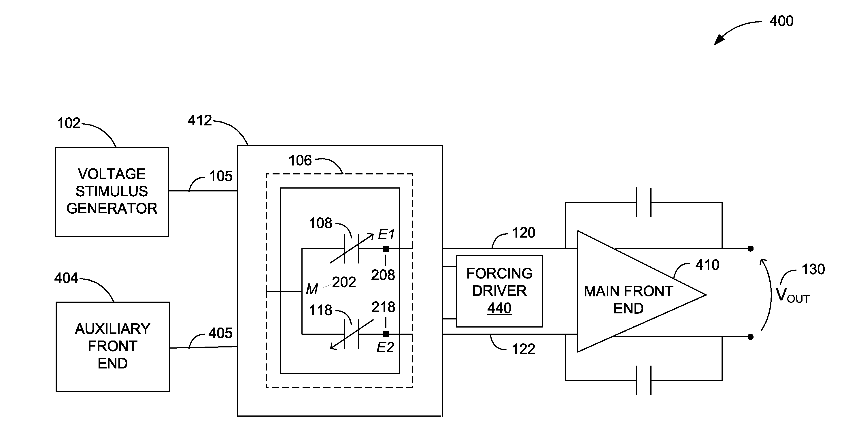
Various embodiments of the invention provide for stiction testing in MEMS devices, such as accelerometers. In certain embodiments, testing is accomplished by a high voltage smart circuit that enables an analog front-end circuit to accurately read the position of a movable proof-mass relative to a biased electrode in order to allow the detection of both contact and release conditions. Testing allows to detect actual or potential stiction failures and to reject defective parts in a Final Test stage of a manufacturing process where no other contributors to stiction issue can occur, thereby, minimizing stiction failure risks and extending the reliability of MEMS devices.

Description

CROSS REFERENCE TO RELATED PATENT APPLICATIONS[0001]The present application claims priority to U.S. Provisional Application Ser. No. 61 / 887,880, titled “Systems and Methods to Determine Stiction Failures in MEMS Devices,” filed on Oct. 7, 2013 by Giorgio Massimiliano Membretti, Roberto Casiraghi, and Igino Padovani, which application is hereby incorporated herein by reference in its entirety.BACKGROUND[0002]A. Technical Field[0003]The present invention relates to integrated micromechanical systems and, more particularly, to systems, devices, and methods of reducing stiction failures in Micro Electro Mechanical System (MEMS) sensors.[0004]B. Background of the Invention[0005]Stiction phenomena are well-known problems in MEMS type devices with movable parts. Stiction effects typically occur between two surfaces when an external force deflects a movable part in a manner so as to cause its surface to come in physical contact and adhere to the surface of an adjacent stationary part.[0006]...

Claims


Application Information

Patent Timeline
IPC IPC(8): G01P15/125
CPCG01P15/125G01P21/00G01P2015/0871G01P2015/0874B81C1/00976
Inventor MEMBRETTI, GIORGIO MASSAMILIANOCASIRAGHI, ROBERTOPADOVANI, IGINO
Owner HANKING ELECTRONICS LTD
Learn More