Manifolds for providing hydraulic fluid to a subsea blowout preventer and related methods

a blowout preventer and hydraulic fluid technology, applied in the field of manifolds, can solve the problems of requiring a large amount of time, requiring costly repairs and/or replacements of malfunctioning components, and current systems for providing hydraulic fluid to such blowout preventer devices may not be configured to provide hydraulic fluid from redundant pressure sources, etc., to facilitate coupling and/or decoupling, the effect of facilitating repair and/or replacemen

Active Publication Date: 2015-04-09
TRANSOCEAN INNOVATION LABS
View PDF21 Cites 27 Cited by
  • Summary
  • Abstract
  • Description
  • Claims
  • Application Information

AI Technical Summary

Benefits of technology

[0012]Some embodiments of the present manifolds are configured (through a subsea valve module having one or more inlets and at least two outlets, the subsea valve module configured to allow each outlet to be in simultaneous fluid communication with a same one of the inlets) to facilitate the coupling and / or decoupling of additional subsea valve modules and / or other components to the subsea valve module (e.g., via a coupling to one or more of the at least two outlets of the subsea valve module) (e.g., to facilitate repair and / or replacement of the manifold, a portion of the manifold, and / or components of the manifold, assembly of the manifold, and / or the like).

Problems solved by technology

Current systems for providing hydraulic fluid to such blowout preventer devices may contain single point of failure components that can render one or more blowout preventer devices partially or completely inoperable upon failure of the component.
Such current systems may also require relatively complex, time-intensive, and costly repairs and / or replacements of malfunctioning components, in some cases, necessitating replacement of large assemblies of components, many of which may be otherwise functional.
And, in some instances, such repairs and / or replacements may require cessation of well operations.
Current systems for providing hydraulic fluid to such blowout preventer devices may also not be configured to provide hydraulic fluid from redundant pressure sources.

Method used


Image

  • Manifolds for providing hydraulic fluid to a subsea blowout preventer and related methods
  • Manifolds for providing hydraulic fluid to a subsea blowout preventer and related methods
  • Manifolds for providing hydraulic fluid to a subsea blowout preventer and related methods

Examples


Embodiment Construction

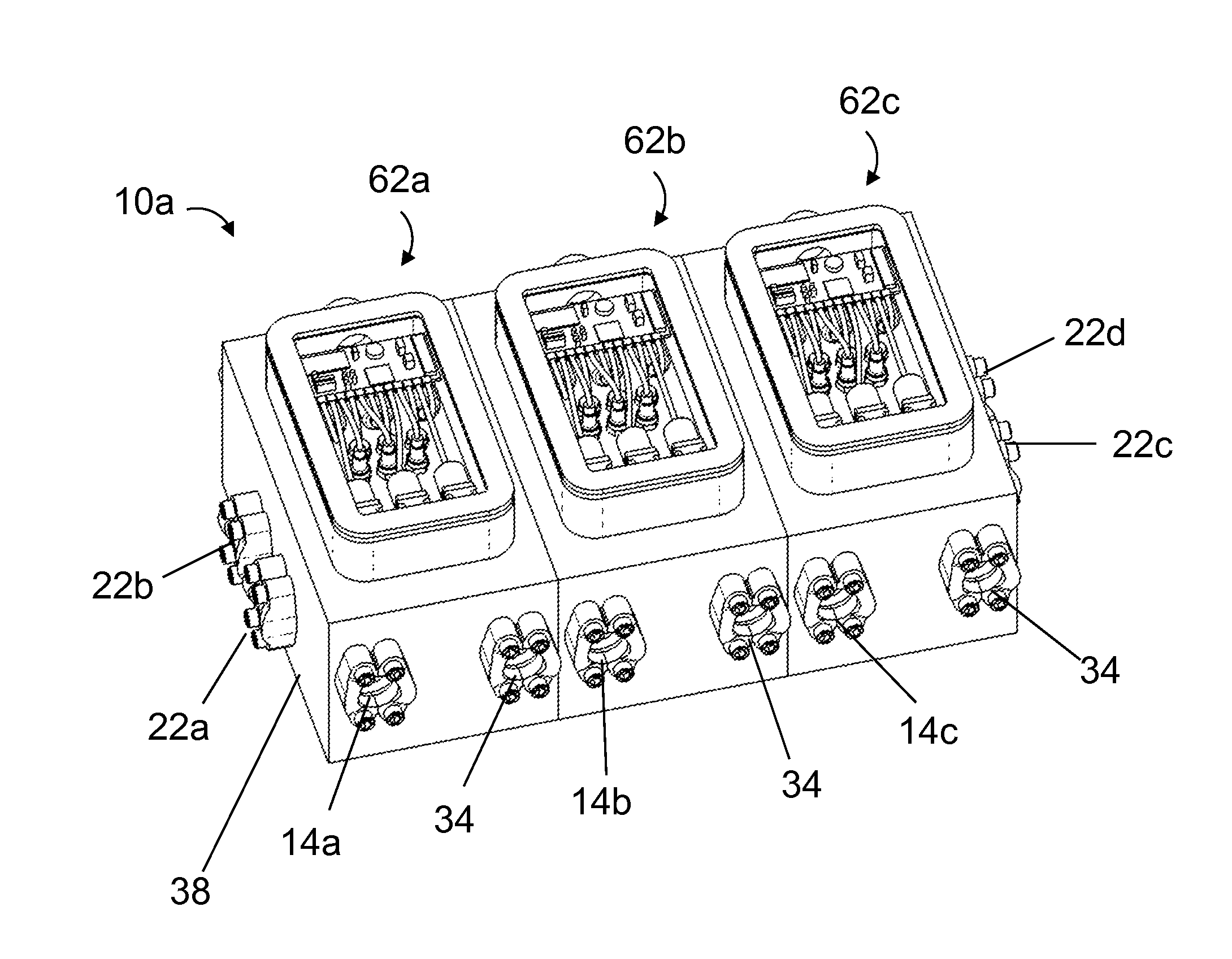
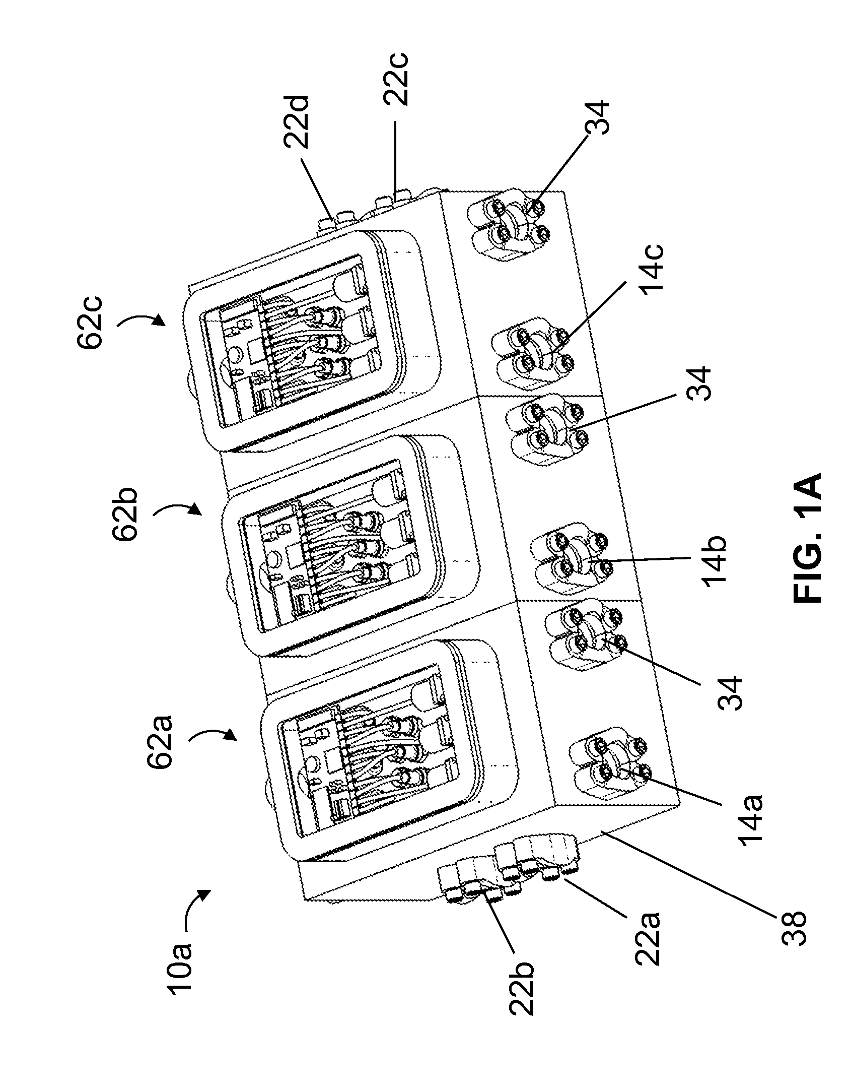
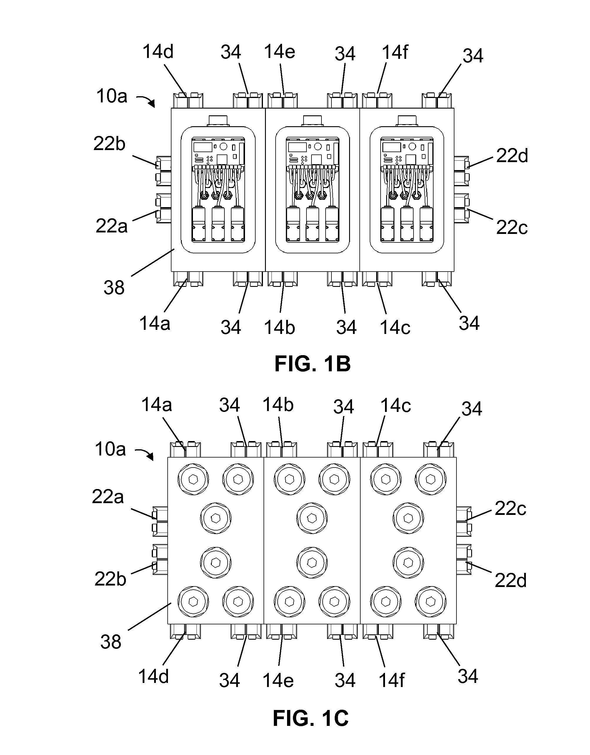
[0072]Referring now to the drawings, and more particularly to FIGS. 1A-1H and 2A-2C, shown therein and designated by the reference numeral 10a is a first embodiment of the present manifolds. In the embodiment shown, manifold 10a comprises at least two inlets (e.g., 14a and 14b) (e.g., six (6) inlets, as shown), sometimes referred to collectively as “inlets 14,” each configured to receive hydraulic fluid from a fluid source (e.g., 18a and / or 18b) (described in more detail below). As used in this disclosure, an “inlet” of a manifold refers to a structure of the manifold configured to receive hydraulic fluid from a fluid source such that the manifold can convey the hydraulic fluid to a hydraulically actuated device of a blowout preventer.

[0073]In this embodiment, as shown, at least two inlets 14 are configured to receive hydraulic fluid from respective (e.g., separate) fluid sources. As used in this disclosure, a fluid source includes, but is not limited to, a pressure source, and a pr...


PUM


Abstract

This disclosure includes manifolds, subsea valve modules, and related methods. Some manifolds and/or subsea valve modules include one or more inlets, each configured to receive hydraulic fluid from a fluid source, one or more outlets, each in selective fluid communication with at least one of the inlets, and one or more subsea valve assemblies, each configured to selectively control hydraulic fluid communication from at least one of the inlets to at least one of the outlets, where at least one of the outlets is configured to be in fluid communication with an actuation port of the hydraulically actuated device.

Description

CROSS-REFERENCE TO RELATED APPLICATIONS[0001]This application claims priority to: (1) U.S. Provisional Application No. 61 / 887,825, filed on Oct. 7, 2013 and entitled “BI-STABLE CONTROL VALVES FOR SUBSEA APPLICATIONS;” (2) U.S. Provisional Application No. 61 / 887,728, filed on Oct. 7, 2013 and entitled “INTEGRATED PILOT AND MAIN STAGE VALVES FOR USE IN SUBSEA APPLICATIONS;” and (3) U.S. Provisional Application No. 61 / 887,698, filed on Oct. 7, 2013 and entitled “INTEGRATED ACTUATION AND INSTRUMENTATION OF VALVES IN SUBSEA APPLICATIONS.” Each of the foregoing provisional patent applications is incorporated by reference in its entirety.BACKGROUND[0002]1. Field of Invention[0003]The present invention relates generally to subsea blowout preventers, and more specifically, but not by way of limitation, to manifolds configured to, for example, provide hydraulic fluid to a hydraulically actuated device of a subsea blowout preventer.[0004]2. Description of Related Art[0005]A blowout preventer i...

Claims


Application Information

Patent Timeline
Patent Type & Authority Applications(United States)
IPC IPC(8): E21B34/04E21B33/064
CPCE21B33/064E21B34/045E21B34/16E21B33/043
Inventor BABBITT, GUY ROBERT
Owner TRANSOCEAN INNOVATION LABS
Why Eureka
Try Eureka