System for driving the drive wheels of an electric or hybrid vehicle

a technology for electric or hybrid vehicles and drive wheels, applied in the direction of motor deposition, control devices, propulsion parts, etc., can solve the problems of increasing the unsprung mass, and increasing the height of the floor, so as to improve the architecture of low-floor road vehicles

Active Publication Date: 2015-04-09
PANTERO TECH
View PDF15 Cites 20 Cited by
  • Summary
  • Abstract
  • Description
  • Claims
  • Application Information

AI Technical Summary

Benefits of technology

[0007]According to one aspect of the invention, a drive system is proposed in order to improve the architecture of low-floor road vehicles by taking advantage of an electric power train.

Problems solved by technology

The result of this type of arrangement is a large space requirement at the center of the vehicle, which generates a higher height of the floor and a significant unsprung mass.
This type of arrangement constitutes a simple development of the inverted-portal axle concept and, among others, has the disadvantage of increasing the unsprung mass.
Furthermore, although an electronic differential can be produced today, it remains complex, expensive and subject to the failure of electronic components.
This type of arrangement makes it possible to lower the floor slightly, but not sufficiently in comparison with the inverted portal approach, and above all to reduce the unsprung mass.
The Hender arrangement offers advantages in terms of the electric drive, but does not however make possible an arrangement for a low-floor vehicle, and it also induces in an increase of the unsprung mass.

Method used


Image

  • System for driving the drive wheels of an electric or hybrid vehicle
  • System for driving the drive wheels of an electric or hybrid vehicle
  • System for driving the drive wheels of an electric or hybrid vehicle

Examples


Embodiment Construction

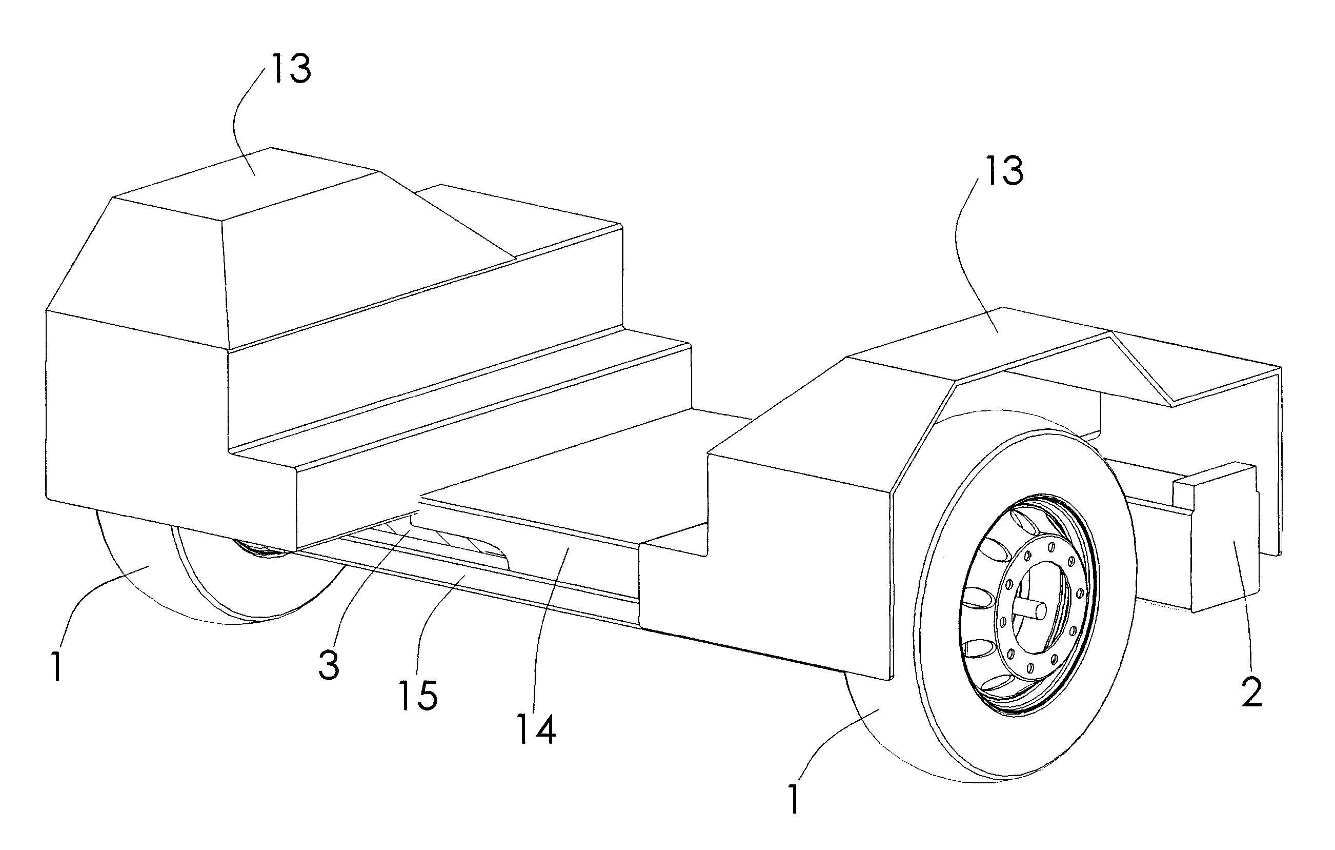
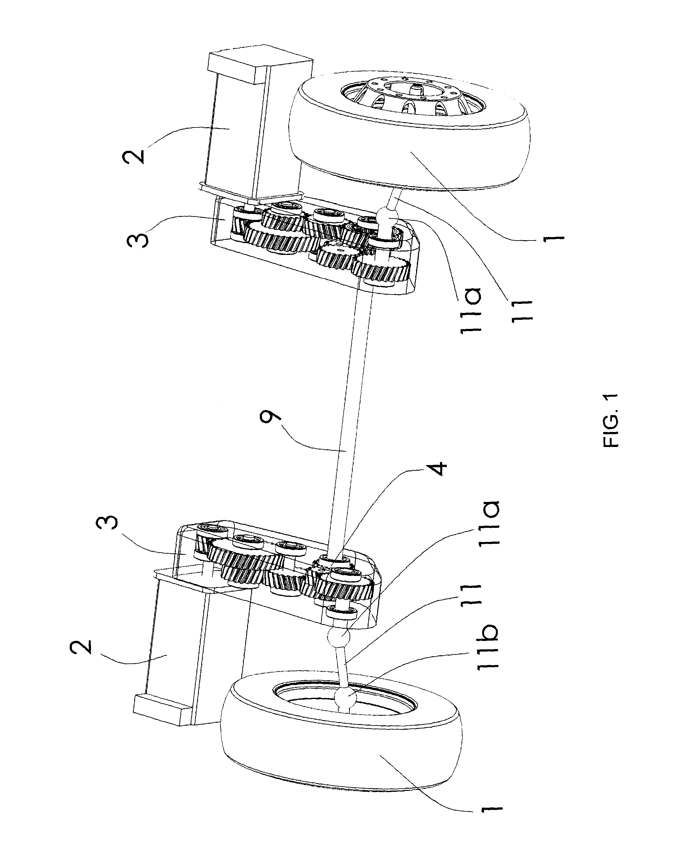
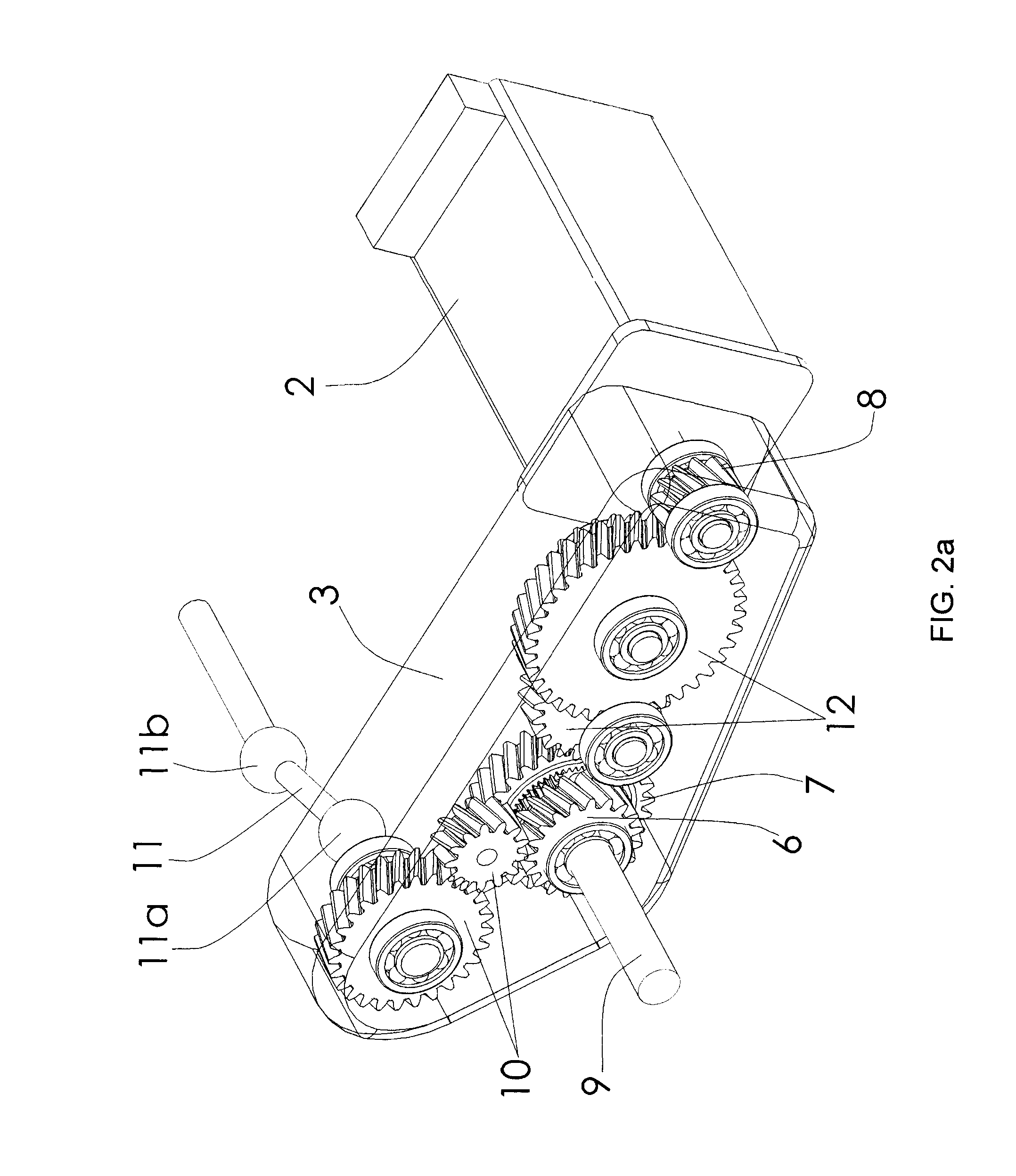
[0020]FIG. 1 illustrates a system for driving the drive and optionally steer wheels (1) of a vehicle. The system generally includes two drive devices mechanically connected for jointly driving at least one left drive wheel and one right drive wheel which are connected by a non-driving axle. As described in more detail below, the drive devices are attached to the sprung mass of the vehicle hereafter called chassis frame in a generic sense, which includes a chassis frame separate from the body as well as an integral chassis or any other component of a chassis such as a sub-frame. Each device includes an electric motor (2) and a casing (3). The motors (2) can be mounted on their respective casing (3) behind the wheels (1). As illustrated in FIGS. 2 to 5, each of the casings (3) includes an input pinion (8) rotatably secured to a rotor of a respective electric motor (2). Each casing (3)—left and right—includes an epicyclic gear train (4) in which a wheel toothed on the outside and on th...


PUM


Abstract

The invention relates to a system for driving the drive wheels (1) of a vehicle, comprising two sets of electric motors (2) and casings (3) (left and right). Each of the casings (3) comprises an input pinion (8) which rotates interdependently with the rotor of one of the electric motors (2) as well as with a set of gears (12) driving the ring gear (7) of a planetary gear set (4). The two planetary gear sets (4) are connected to one another by a connecting means (9) that rotates interdependently with each of the two sun gears (5) (inner planetaries). The planet carrier (6) of each of the planetary gear sets (4) rotates interdependently with a connecting means (11) of one of the drive wheels (1). The two planetary gear sets (4) perform a double differential function. The invention also relates to a method for controlling the electric motors (2) that allows the drive system to be used as a torque converter. The drive system can be fixed to the chassis frame of the vehicle. In addition, the two casings (3) can be located in the wheel cages (13). The connecting means (9) that rotates interdependently with the two sun gears (5) can be located inside the casing of the floor pan (14) of the vehicle. The two electric motors (2) can be located just behind the driven wheels (1).

Description

TECHNICAL FIELD[0001]The present invention relates to a system for driving the drive and optionally steer wheels of an electric or hybrid vehicle.PRIOR ART[0002]Historically, the rear axle of the urban buses has been inspired by the rear axle of heavy trucks in which one finds an imposing differential at the center of a driving axle that puts the wheels in rotation. The result of this type of arrangement is a large space requirement at the center of the vehicle, which generates a higher height of the floor and a significant unsprung mass.[0003]Commonly today, the low-floor urban buses use an axle concept with inverted portal as described by the patent U.S. Pat. No. 6,035,956, among others, in which the axle shaft and the axle structure, forming a live axle assembly, are offset vertically (downward) from the center of the wheels, and in which speed reduction gears are distributed on each side of the vehicle near the wheels. The notion of a lowered driving axle had already been introd...

Claims


Application Information

Patent Timeline
Patent Type & Authority Applications(United States)
IPC IPC(8): B60K1/02B60K17/30B60K17/14
CPCB60K1/02B60K17/30B60K17/14B60Y2200/1432B60K7/0007B60K17/043B60K2007/0046B60K2007/0061B60K2001/0405B60K2001/0438
Inventor RAYMOND, JEAN
Owner PANTERO TECH
Why Eureka
Try Eureka