
Pixel structure

a pixel structure and pixel technology, applied in the field of pixel structure, can solve the problem of limited viewing angle of liquid crystal display, and achieve the effect of improving the viewing angl

Active Publication Date: 2015-04-09
AU OPTRONICS CORP
View PDF2 Cites 12 Cited by
  • Summary
  • Abstract
  • Description
  • Claims
  • Application Information

AI Technical Summary

Benefits of technology

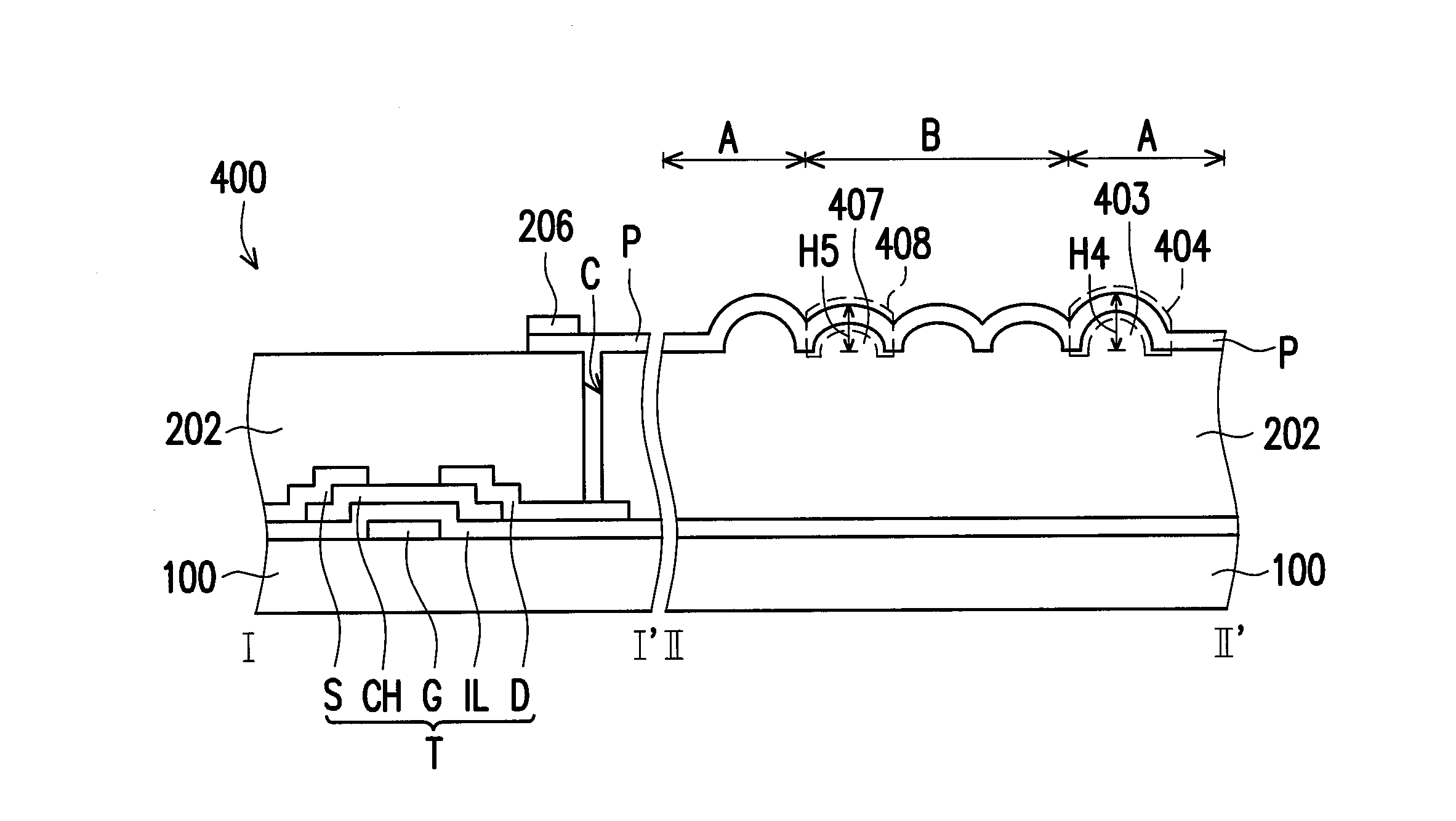
The invention provides a pixel structure that has better reflectance and reflection angle distribution. This is achieved by designing a reflective pixel electrode with protruding structures in two regions. The height of the protruding structures in the first region is greater, and the area occupied by each region is optimized. This results in the pixel structure being able to increase light reflectance and reflection angle distribution of light.

Problems solved by technology

However, the issue of limited viewing angle still remains for the liquid crystal display.

Method used


Image

  • Pixel structure
  • Pixel structure
  • Pixel structure

Examples


Embodiment Construction

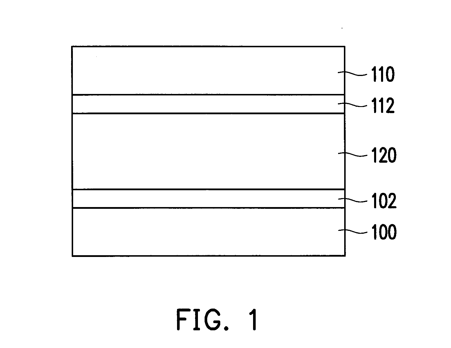
[0023]FIG. 1 is a schematic cross-sectional diagram of a display panel according to an embodiment of the invention.

[0024]Referring to FIG. 1, the display panel of the present embodiment includes a first substrate 100, a second substrate 110, and a display medium 120 disposed between the first substrate 100 and the second substrate 110.

[0025]The first substrate 100 is disposed opposite to the second substrate 110. The material of each of the first substrate 100 and the second substrate 110 can be glass, quartz, an organic polymer, or other suitable materials. The display medium 120 is, for instance, a liquid crystal material. In other words, the display panel of the present embodiment is, for instance, a liquid crystal display panel. However, the invention is not limited thereto. In other embodiments, the display medium 120 can also be other display materials such as an organic light-emitting diode material, an inorganic light-emitting diode material, an electrophoretic display mater...


PUM

PropertyMeasurementUnit
height H1aaaaaaaaaa
height H1aaaaaaaaaa
areaaaaaaaaaaa

Abstract

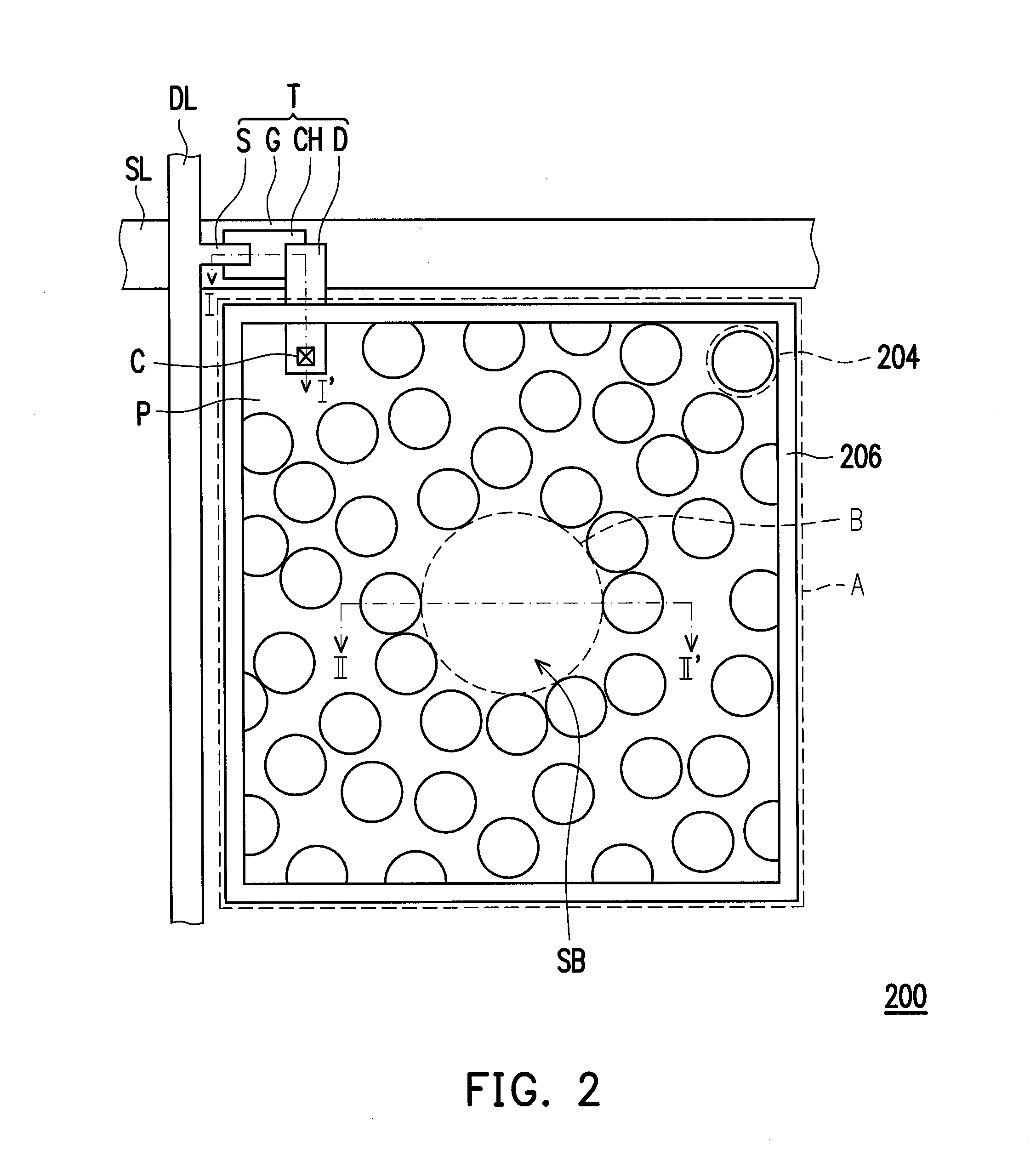
A pixel structure is provided. The pixel structure includes a scan line, a data line, an active device, a covering layer, and a reflective pixel electrode. The active device is electrically connected with the scan line and the data line. The covering layer covers the scan line, the data line, and the active device. The reflective pixel electrode is disposed on the covering layer, and electrically connected with the active device. The reflective pixel electrode includes a first region having a plurality of first protruding structures and a second region having a planar surface. The area occupied by the first region is 50% to 70% of the total area of the reflective pixel electrode, and the area occupied by the second region is 30% to 50% of the total area of the reflective pixel electrode.

Description

CROSS-REFERENCE TO RELATED APPLICATION[0001]This application claims the priority benefit of Taiwan application serial no. 102136238, filed on Oct. 7, 2013. The entirety of the above-mentioned patent application is hereby incorporated by reference herein and made a part of this specification.BACKGROUND OF THE INVENTION[0002]1. Field of the Invention[0003]The invention relates to a pixel structure. More particularly, the invention relates to a pixel structure with total internal reflection.[0004]2. Description of Related Art[0005]In recent years, with the development in optoelectronic technology and semiconductor manufacturing technology, flat panel displays have flourished as a result. Liquid crystal displays, characterized by advantages such as low operating voltage, free of harmful radiation, light weight, and compact size, have replaced conventional cathode ray tube displays and have become mainstream display products. However, the issue of limited viewing angle still remains for ...

Claims


Application Information

Patent Timeline
Patent Type & Authority Applications(United States)
IPC IPC(8): G02F1/1343H01L27/32G02F1/1362
CPCG02F1/13439H01L27/3276G02F1/136227G02F1/136286G02F1/133553H10K59/12H10K59/878H10K59/80518H10K59/80515H10K50/813H10K50/818H10K50/856
Inventor CHEN, YAN-LIANG
Owner AU OPTRONICS CORP
Learn More