Light weight solar concentrator

a solar concentrator and light weight technology, applied in the safety of solar heat collectors, lighting and heating equipment, instruments, etc., can solve the problem of dramatically reducing the structural strength requirement of the framework

Active Publication Date: 2015-04-16
CSPULTRALITESOLAR INC
View PDF2 Cites 7 Cited by
  • Summary
  • Abstract
  • Description
  • Claims
  • Application Information

AI Technical Summary

Problems solved by technology

This weight reduction dramatically reduces the structural streng

Method used


Image

  • Light weight solar concentrator
  • Light weight solar concentrator
  • Light weight solar concentrator

Examples


Embodiment Construction

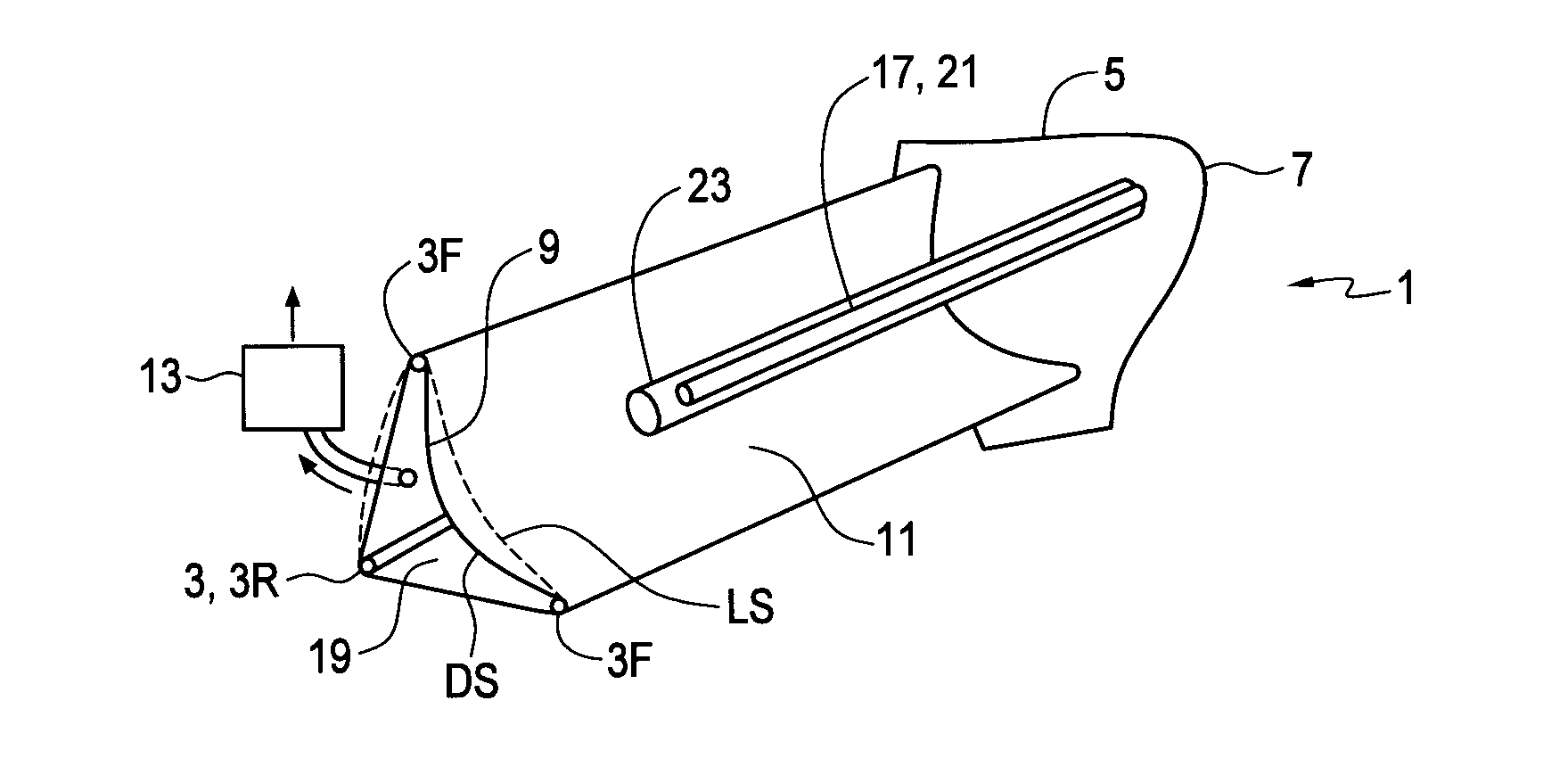
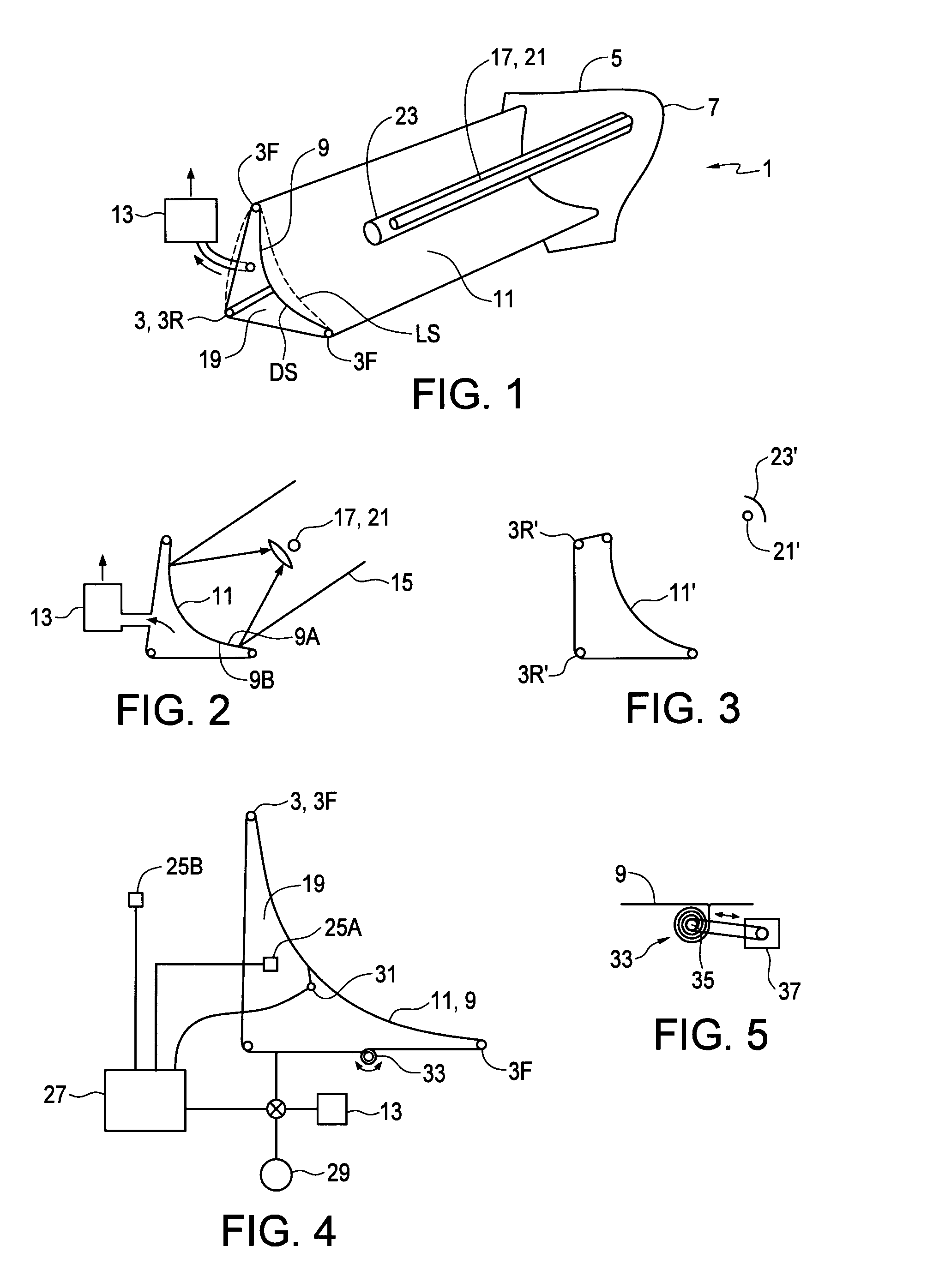
[0035]FIGS. 1 and 2 schematically illustrate sectional views of an embodiment of a solar concentrator apparatus 1 of the present invention. The apparatus 1 comprises a plurality of frame members 3 connected together to form a framework 5. In the illustrated apparatus 1 the framework comprises substantially parallel upper and lower front frame members 3F extending between right and left ends of the framework 5, and a rear frame member 3R extending between the right and left ends of the framework 5 parallel to the upper and lower front frame members 3F. The frame members 3F, 3R are attached to endplates 7 at each end of the framework 5.

[0036]A flexible sheet 9 is attached to the framework 5 such that the flexible sheet 9 takes a loose shape LS, indicated by the dotted lines in FIG. 1, and can flex in response to shaping forces exerted thereon. The flexible sheet 9 has a reflective surface 11 located between the upper and lower front frame members 3F.

[0037]A shaping force system 13 is ...


PUM

PropertyMeasurementUnit
Pressureaaaaaaaaaa
Flexibilityaaaaaaaaaa
Radiusaaaaaaaaaa

Abstract

A solar concentrator has frame members connected together to form a framework, and a flexible sheet attached to the framework such that the flexible sheet takes a loose shape and can flex in response to shaping forces exerted thereon. The sheet has a reflective surface located between the frame members. A shaping force system is operative, when activated, to exert the shaping forces on the sheet, the shaping forces configured to draw the sheet from the loose shape into a desired shape such that solar rays striking the reflective surface are focused on a target, and a solar energy receiver is attached to the framework at a location corresponding to the target. Thin wall tubing filled with pressurized air can provide strong light frame members. When the shaping force system is deactivated, the flexible sheet reverts substantially to the loose shape.

Description

[0001]This invention is in the field of equipment for collecting and concentrating solar energy and in particular an economical light weight apparatus for collecting and concentrating solar rays.BACKGROUND[0002]Considerable effort is directed to efficiently and effectively harnessing solar energy. Photo voltaic (PV) panels convert received solar rays directly into electrical energy, while thermal systems concentrate solar rays to produce heat, which can be used directly for heating purposes, or is used to produce rotating mechanical power by operating a Stirling engine for example, or more commonly by creating steam to operate a steam turbine, which can then be used to produce electrical power. Solar power may also be concentrated on a PV panel to increase the amount of solar energy received on a given area of panel, and thus increase the power generated from the panel.[0003]A typical solar collection and concentration system uses mirrors to reflect solar rays from a wide area onto ...

Claims


Application Information

Patent Timeline
IPC IPC(8): H01L31/054H01L31/18G02B7/183H01L31/052F24S10/70F24S23/00F24S23/30F24S23/74
CPCH01L31/0547H01L31/0521H02S20/32H01L31/18G02B7/183Y02E10/52Y10T29/49355F24S23/30F24S23/745F24S40/85Y02E10/40
Inventor BECK, JAMES THOMAS
Owner CSPULTRALITESOLAR INC
Why Eureka
Try Eureka