Laser sintering powder, method for producing structure, apparatus for producing structure
Inactive Publication Date: 2015-04-16
SEIKO EPSON CORP
View PDF14 Cites 36 Cited by
Summary
Abstract
Description
Claims
Application Information
AI Technical Summary
This helps you quickly interpret patents by identifying the three key elements:
Problems solved by technology
Method used
Benefits of technology
Benefits of technology
The patent describes the use of a laser sintering powder where metal particles are attached to each other by a binder. When the powder is exposed to laser light, the binder decomposes and the metal particles separate from each other. The metal particles become heated by the laser and can be reliably sintered even in a deep region. The roller used in the process is simple and small, making it easy to produce the desired structure. The technical effect of this patent is that it provides a more efficient and effective method for producing structures using laser sintering powder.
Problems solved by technology
Unfortunately, fine metal powder is easily stirred up in the air.
Thus, although a minute structure can be obtained by laser sintering, the minute structure may have a surface which a polishing tool or a polishing cloth cannot reach, and therefore, it is difficult to make the surface glossy.
Method used
Image
Click on the blue label to locate the original text in one second.
Reading with bidirectional positioning of images and text.
Examples
second embodiment
[0110]Next, a second embodiment of the method for producing a structure according to the invention will be described.
[0111]Hereinafter, a second embodiment will be described, however, in the following description, different points from the first embodiment will be mainly described, and the description of the same matter will be omitted. Further, in the drawings, the same components as in the above-described embodiment will be given the same reference numerals.
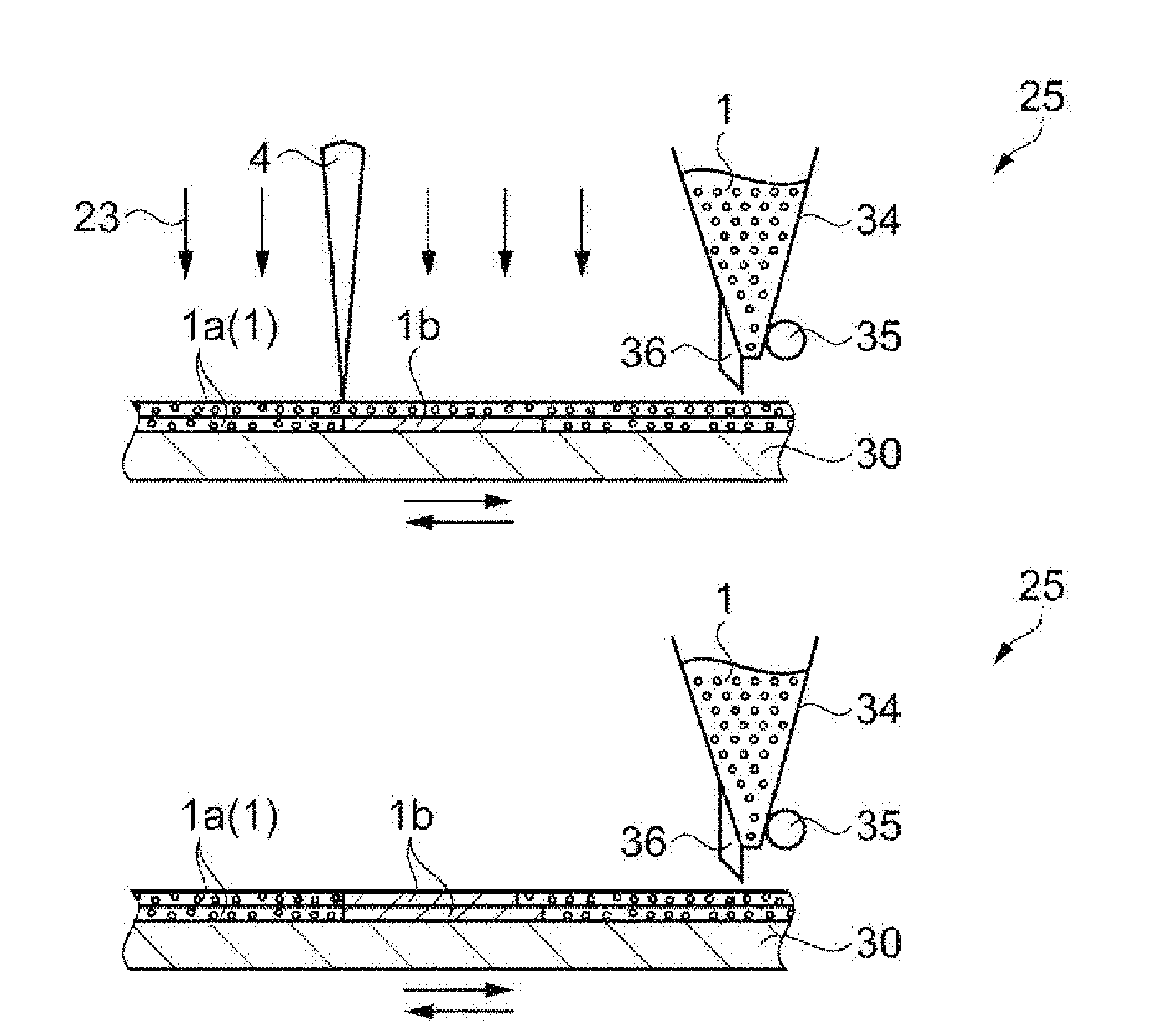
[0112]FIGS. 8A to 8F and FIGS. 9A to 9E are schematic views for explaining a method for forming a structure using a laser sintering powder (a second embodiment of the method for producing a structure according to the invention), respectively. Hereinafter, with reference to FIGS. 8A to 8F and FIGS. 9A to 9E, the method for forming a structure will be described. In this method, a laser sintering apparatus 25 (a second embodiment of the apparatus for producing a structure according to the invention) shown in FIG. 7 is used.
[0113]F...
third embodiment
[0133]Next, a third embodiment of the method for producing a structure according to the invention will be described.
[0134]Hereinafter, a third embodiment will be described, however, in the following description, different points from the second embodiment will be mainly described, and the description of the same matter will be omitted. Further, in the drawings, the same components as in the above-described embodiments will be given the same reference numerals.
[0135]FIGS. 10A to 10F and FIGS. 11A to 11E are schematic views for explaining a method for forming a structure using a laser sintering powder (a third embodiment of the method for producing a structure according to the invention), respectively. Hereinafter, with reference to FIGS. 10A to 10F and FIGS. 11A to 11E, the method for forming a structure will be described. Also in this method, the laser sintering apparatus 25 shown in FIG. 7 is used.
[0136]The third embodiment is the same as the second embodiment except that the timin...
modification example 1
[0179]In the embodiments described above, the powder layer 1a is sintered by irradiating the powder layer 1a with the laser light 4. However, the sintered layer 1b may be further heated. By doing this, a structure 49 having high peeling resistance strength can be obtained.
PUM
Property
Measurement
Unit
Particle diameter
aaaaa
aaaaa
Particle diameter
aaaaa
aaaaa
Particle diameter
aaaaa
aaaaa
Abstract
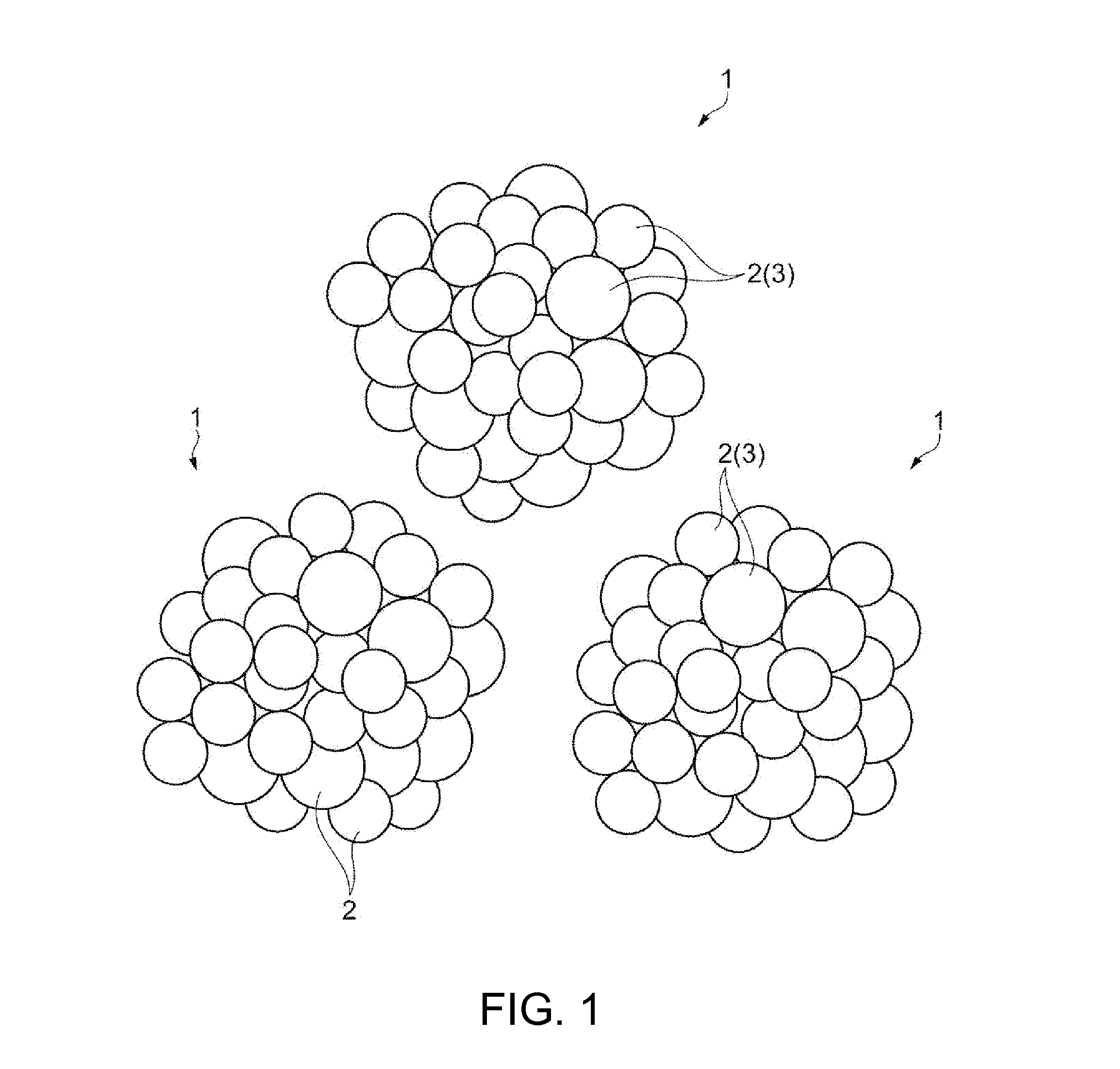
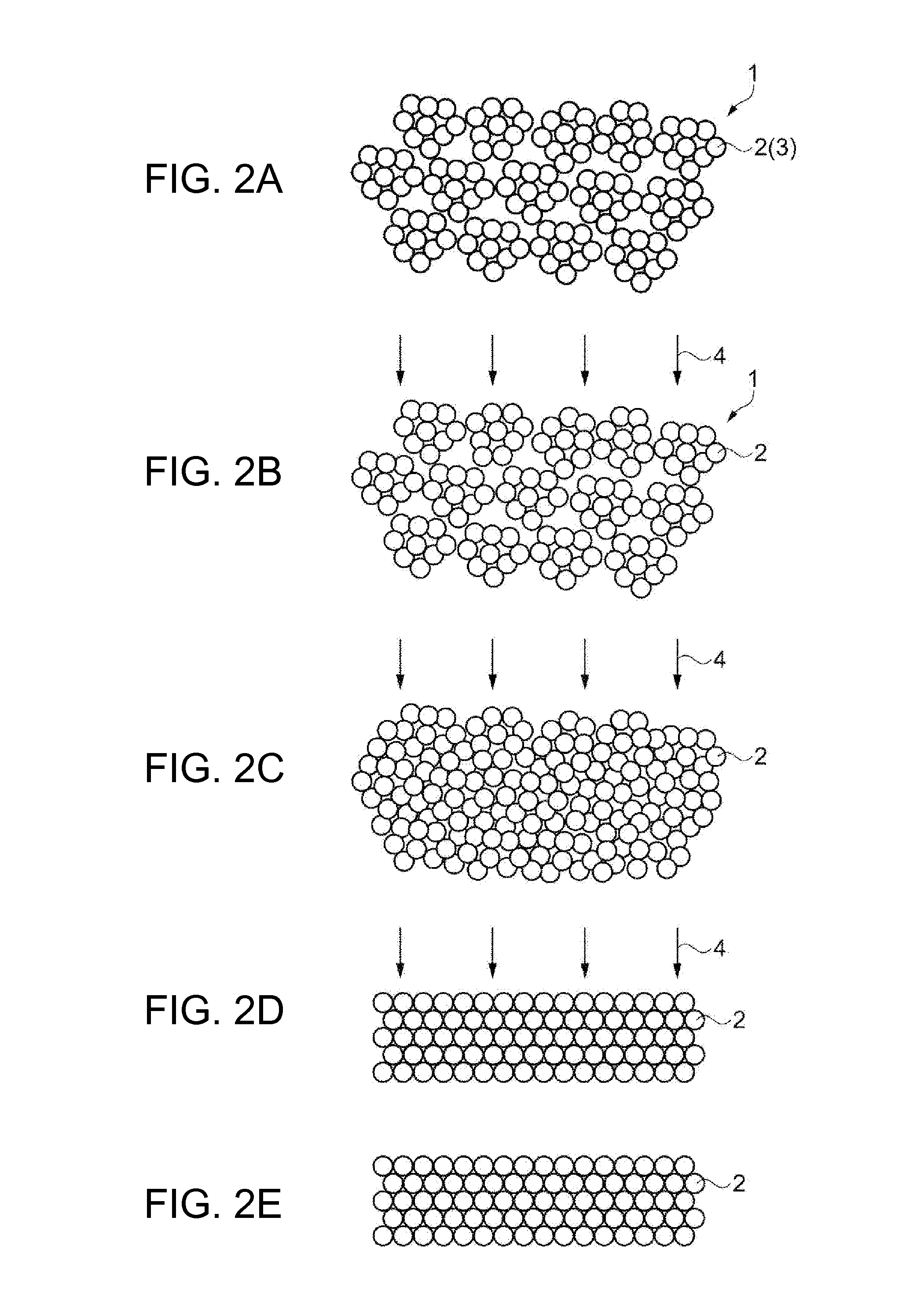
A lasersinteringpowder to be sintered by irradiation with a laser light is provided. The sinteringpowder includes a plurality of metal particles and a binder which binds the metal particles to one another. The binder is sublimated by the irradiation with the laser light. The average particle diameter of the metal particles is 5 μm or more and 10 μm or less, and the average particle diameter of the laser sinteringpowder is 30 μm or more and 50 μm or less. Further, after a powder layer is formed using the laser sintering powder, this powder layer may be compressed in the thickness direction before or after irradiation with the laser light.
Description
BACKGROUND[0001]1. Technical Field[0002]The present invention relates to a laser sintering powder, a method for producing a structure, and an apparatus for producing a structure.[0003]2. Related Art[0004]A production method for forming a structure by irradiating a metal powder with a laser light is known. This method is suitable for the production of small amounts of various structures because the structure is formed by controlling a laser light using a computer. One such production method is disclosed in JP-T-2001-504897. According to this method, first, a metal powder is spread on a flat plate. Subsequently, a leveling plate is moved along the surface of the metal powder layer to level the metal powder to a given uniform thickness. Subsequently, a protection gas is flowed over the metal powder layer to create a protection gas atmosphere. Subsequently, a laser light is formed into a beam and scanned across the metal powder layer to draw a given image. In a region irradiated with th...
Claims
Application Information
Patent Timeline
Application Date:The date an application was filed.
Publication Date:The date a patent or application was officially published.
First Publication Date:The earliest publication date of a patent with the same application number.
Issue Date:Publication date of the patent grant document.
PCT Entry Date:The Entry date of PCT National Phase.
Estimated Expiry Date:The statutory expiry date of a patent right according to the Patent Law, and it is the longest term of protection that the patent right can achieve without the termination of the patent right due to other reasons(Term extension factor has been taken into account ).
Invalid Date:Actual expiry date is based on effective date or publication date of legal transaction data of invalid patent.

