
Methods and Processes of Coating Zero-PGM Catalysts including with Cu, Mn, Fe for TWC Applications

Inactive Publication Date: 2015-04-16
CLEAN DIESEL TECHNOLOGIES
View PDF3 Cites 22 Cited by
  • Summary
  • Abstract
  • Description
  • Claims
  • Application Information

AI Technical Summary

Benefits of technology

The patent text explains that the chemical composition of a catalyst can affect its performance in operation. This is particularly important for ZPGM catalysts, which can be made using PGM-free materials. By using different coating processes, the TWC property of the catalyst can be improved, which can save time and money for manufacturers.

Problems solved by technology

As an ineffectual coating technique may result in heterogeneity of the applied coating, the preparation path for coatings may show critical factors which can influence the coating quality and catalytic performance.

Method used


Image

  • Methods and Processes of Coating Zero-PGM Catalysts including with Cu, Mn, Fe for TWC Applications
  • Methods and Processes of Coating Zero-PGM Catalysts including with Cu, Mn, Fe for TWC Applications
  • Methods and Processes of Coating Zero-PGM Catalysts including with Cu, Mn, Fe for TWC Applications

Examples


example # 1

Example #1

Coating Process Type 1, Cu—Mn—Fe Spinel Bulk Powder / Nb2O5-ZrO2 Support Oxide

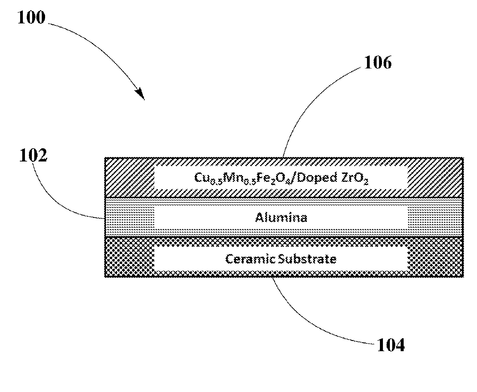
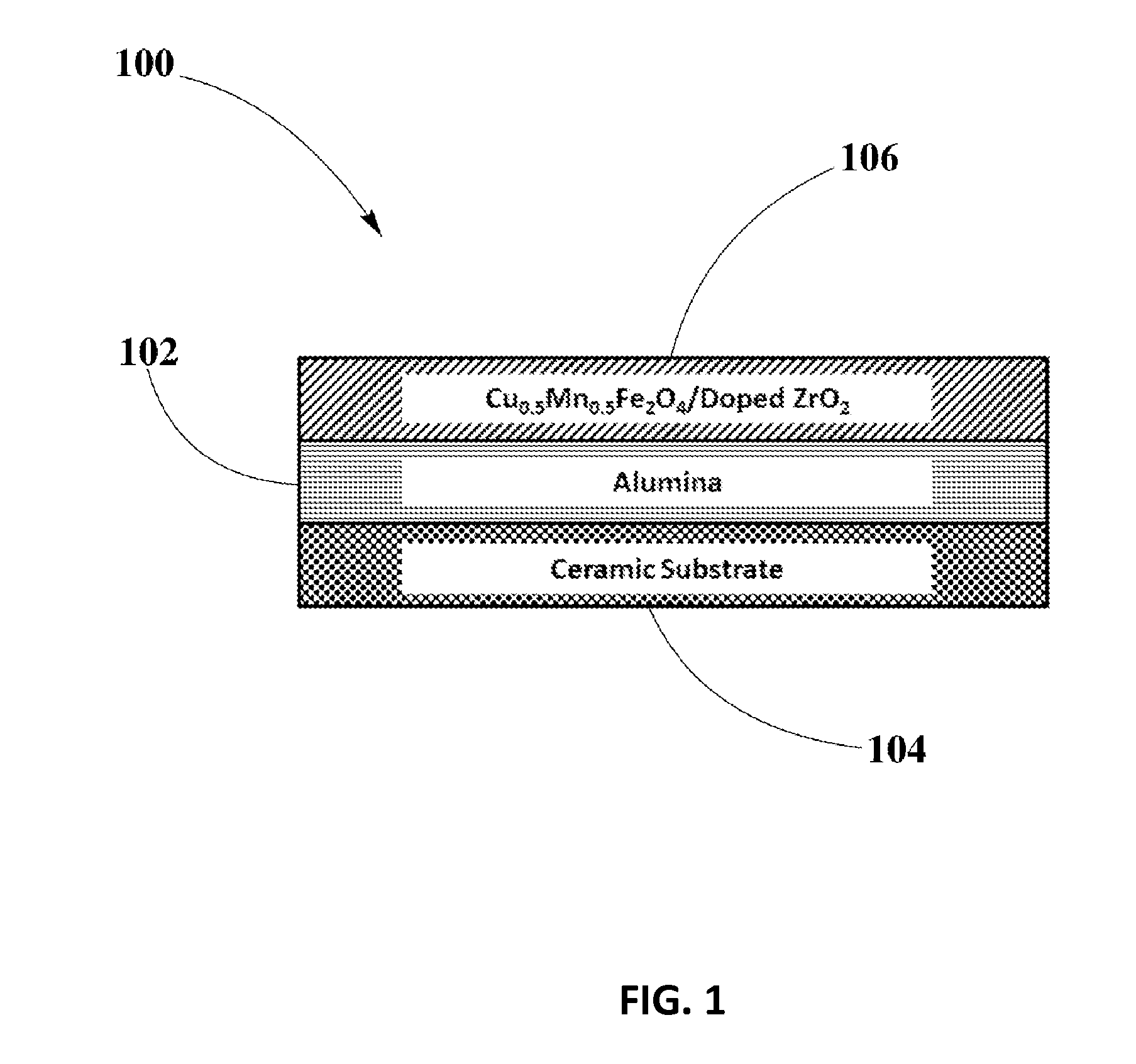
[0057]Example #1 may illustrate preparation of fresh and aged ZPGM catalyst samples of catalyst configuration 100 employing coating process here referred as coating process Type 1. Aged catalyst samples may be prepared by hydrothermal aging employing about 10% steam / air at a plurality of temperatures within a range from about 800° C. to about 1,000° C. for about 4 hours. In this embodiment, hydrothermally aged samples may be preferably aged at 900° C. for about 4 hours.

[0058]Preparation of WC layer 102 may start by milling alumina to make slurry. Suitable loading of alumina may be about 120 g / L. Alumina slurry may be subsequently coated on ceramic substrate 104 and fired at about 550° C. for about 4 hours. Preparation of OC layer 106 may start by milling Nb2O5-ZrO2 support oxide with water separately to make slurry. Then, Cu—Mn—Fe solution may be prepared by mixing the appropriate amount of Cu nitr...

example # 2

Example #2

Coating process Type 2, IMP of Cu—Mn—Fe Spinel on Nb2O5-ZrO2 Support Oxide

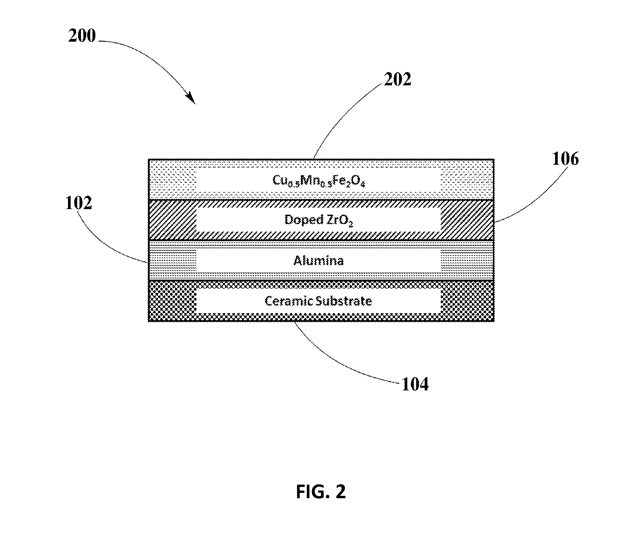
[0061]Example #2 may illustrate preparation of fresh and aged ZPGM catalyst samples of catalyst configuration 200 employing coating process here referred as coating process Type 2. Aged catalyst samples may be prepared by hydrothermal aging employing about 10% steam / air at a plurality of temperatures within a range from about 800° C. to about 1,000° C. for about 4 hours. In this embodiment, hydrothermally aged samples may be preferably aged at 900° C. for about 4 hours.

[0062]Preparation of WC layer 102 may start by milling alumina to make slurry. Suitable loading of alumina may be about 120 g / L. Alumina slurry may be subsequently coated on ceramic substrate 104 and fired at about 550° C. for about 4 hours. Preparation of OC layer 106 may start by milling Nb2O5-ZrO2 support oxide with water separately to make slurry. Slurry of Nb2O5-ZrO2 support oxide may then be coated on WC layer 102 and fired at ab...


PUM

PropertyMeasurementUnit
Fractionaaaaaaaaaa
Fractionaaaaaaaaaa
Stabilityaaaaaaaaaa

Abstract

Variations of coating processes of Cu—Mn—Fe ZPGM catalyst materials for TWC applications are disclosed. The disclosed coating processes for Cu—Mn—Fe spinel materials are enabled in the preparation ZPGM catalyst samples according to a plurality of catalyst configurations, which may include an alumina only washcoat layer coated on a suitable ceramic substrate, and an overcoat layer with or without an impregnation layer, including Cu—Mn—Fe spinel and doped Zirconia support oxide, prepared according to variations of disclosed coating processes. Activity measurements are considered under variety of lean condition to rich condition to analyze the influence of disclosed coating processes on TWC performance of ZPGM catalysts for a plurality of TWC applications. Different coating processes may substantially increase thermal stability and TWC activity, providing improved levels of NOx conversion that may lead to cost effective manufacturing solutions for ZPGM-TWC systems.

Description

CROSS-REFERENCE TO RELATED APPLICATIONS[0001]This application is a continuation-in-part of U.S. patent application Ser. No. 13 / 849169, filed Mar. 23, 2013, entitled “Methods for Oxidation and Two-way and Three-way ZPGM Catalyst Systems and Apparatus Comprising Same,” now Pat. No. 8,858,903, issued Oct. 14, 2014, which is incorporated herein by reference as if set forth in its entirety.BACKGROUND[0002]1. Field of the Disclosure[0003]This disclosure relates generally to catalyst materials, and more particularly, to the influence of a plurality of coating processes, for catalyst materials including Cu-Mn-Fe ternary spinel systems on support oxides, upon performance of Zero-PGM catalysts for TWC applications.[0004]2. Background Information[0005]Catalyst attributes of activity, stability, selectivity, and regenerability in long-term service can be related to the physical and chemical properties of the catalyst materials, which in turn can be related to the method of preparation of the ca...

Claims


Application Information

Patent Timeline
IPC IPC(8): B01J23/889B01J23/20
CPCB01J23/8892B01J23/20B01D53/945B01D2255/207B01D2255/20715B01D2255/2073B01D2255/20761B01D2255/405B01D2255/65B01J2523/00Y02T10/12Y10S502/52712B01J2523/17B01J2523/72B01J2523/842
Inventor NAZARPOOR, ZAHRAGOLDEN, STEPHEN J.
Owner CLEAN DIESEL TECHNOLOGIES
Learn More