
Non-aqueous electrolyte battery

a non-aqueous electrolyte, battery technology, applied in secondary cell servicing/maintenance, cell components, sustainable manufacturing/processing, etc., can solve the problems of electrolyte solution's infiltrating performance into the interior of the electrode, battery safety to degrade, and battery capacity improvement has made little progress in recent months, etc., to achieve the highest resistance rate, low current collection performance, and high reactivity

Inactive Publication Date: 2006-01-26
SANYO ELECTRIC CO LTD
View PDF8 Cites 53 Cited by
  • Summary
  • Abstract
  • Description
  • Claims
  • Application Information

AI Technical Summary

Benefits of technology

[0012] Accordingly, it is an object of the present invention to provide a non-aqueous electrolyte battery that achieves improvements in safety, particularly in tolerance of the battery to overcharging, without compromising conventional battery constructions considerably.
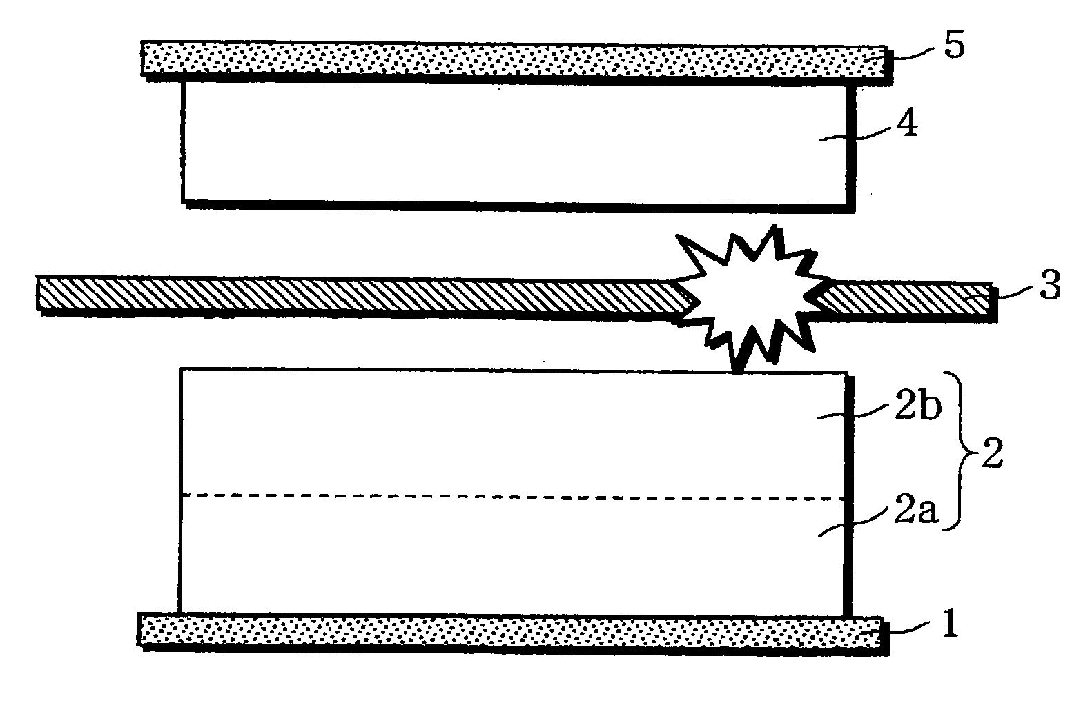
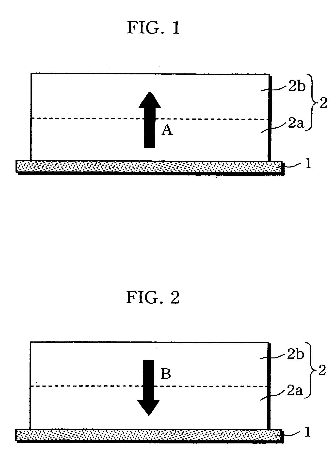
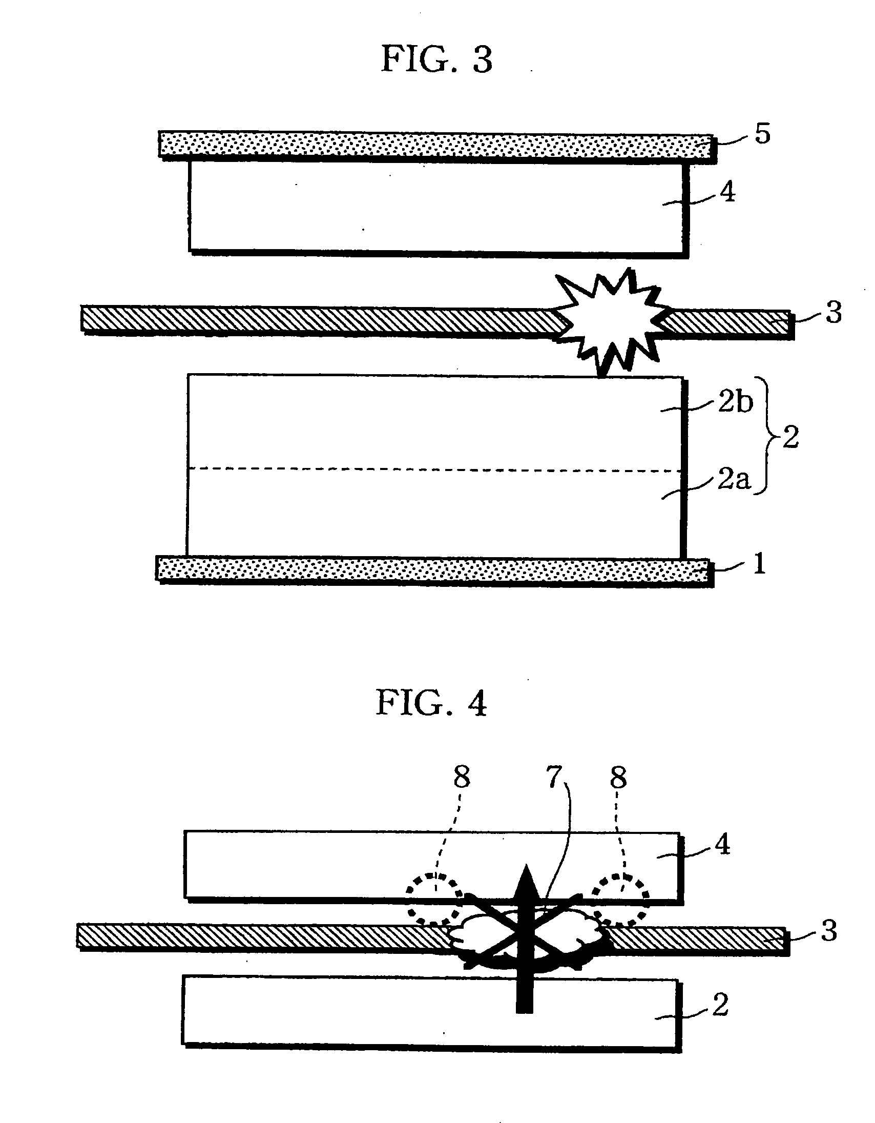
[0014] When, as in the foregoing construction, a layer other than the outermost positive electrode layer contains as its main active material the positive electrode active material having the highest resistance increase rate during overcharge among the positive electrode active materials, the current collection performance lowers in the outermost positive electrode layer, which has a high reactivity during overcharge, inhibiting the active material of the outermost positive electrode layer from being charged to the charge depth that is to be reached originally. Accordingly, the amount of lithium deintercalated from the positive electrode in the overcharge region (especially the amount of lithium deintercalated from the outermost positive electrode layer) reduces, causing the total amount of lithium deposited on the negative electrode to reduce. Consequently, the amount of heat produced due to the reaction between the electrolyte solution and the lithium deposited on the negative electrode reduces, thereby preventing the deposition of dendrite. Moreover, the thermal stability of the positive electrode active material (particularly of the active material in the outermost positive electrode layer that becomes instable because of the extraction of lithium from the crystals) is also kept relatively high because the charge depth does not become deep; therefore, the reaction between the positive electrode active material and the excessive electrolyte solution existing in the separator etc. can be inhibited. For the above reasons, the tolerance of the battery to overcharging can be improved remarkably.

Problems solved by technology

Nevertheless, increasing the filling density of the positive electrode active material causes battery safety to degrade when the battery is overcharged.
In other words, since there is a trade-off between improvement in battery capacity and enhancement in battery safety, improvements in capacity of the battery have lately made little progress.
Conventional unit cells incorporate various safety mechanisms such as a separator shutdown function and additives to electrolyte solutions, but these mechanisms are designed assuming a condition in which the filling density of active material is not very high.
For that reason, increasing the filling density of active material as described above brings about such problems as follows.
Since the electrolyte solution's infiltrating performance into the interior of the electrodes is greatly reduced, reactions occur locally, causing lithium to deposit on the negative electrode surface.
In addition, the convection of electrolyte solution is worsened and heat is entrapped within the electrodes, worsening heat dissipation.
These prevent the above-mentioned safety mechanisms from fully exhibiting their functions, leading to further degradation in safety.
Therefore, an improvement in safety cannot be attained.
The above-described construction is intended for merely preventing the thermal runaway of a battery due to heat dissipation through the current collector under a certain voltage, and is not effective in preventing the thermal runaway of an active material that originates from deposited lithium on the negative electrode such as when overcharged.

Method used


Image

  • Non-aqueous electrolyte battery
  • Non-aqueous electrolyte battery
  • Non-aqueous electrolyte battery

Examples


embodiments

Preliminary Experiment

[0079] Shutdown temperature (hereinafter also referred to as “SD temperature”) and meltdown temperature (hereinafter also referred to as “MD temperature”) were investigated with the foregoing electron beam cross-linked separator (used in later-described Batteries A1, A4, B1, C1, and D1 of the invention, as well as Comparative Batteries U1, V1, W1, and X1), a heat-proof layer-stacked separator (used in later-described Batteries A2, A5, and D2 of the invention as well as Comparative Batteries U3, V2, W2, X3, Y, and Z), and an ordinary separator (used in later-described Batteries A3, A6, B2, C2, D3, D4, E, and F of the invention as well as Comparative Batteries U3, V2, W2, X3, Y, and Z). The results are shown in Table 1. The method of fabricating test cells, the evaluation equipment, and the method of measuring SD temperature and MD temperature were as follows.

Fabrication Method of Test Cell

[0080] As illustrated in FIG. 5, a substantially square-shaped aluminu...

first embodiment

Example A1

[0088] A battery fabricated in the same manner as described in the foregoing working example was used as Example A1.

[0089] The battery thus fabricated is hereinafter referred to as Battery A1 of the invention.

Example A2

[0090] A battery was fabricated in the same manner as in Example A1 above, except that a heat-proof layer-stacked separator was used in place of the electron beam cross-linked separator.

[0091] The battery thus fabricated is hereinafter referred to as Battery A2 of the invention.

[0092] Herein, the heat-proof layer-stacked separator was fabricated in the following manner.

[0093] First, polyamide (PA), which is a water-insoluble, heat-resistant material, was dissolved in N-methyl-2-pyrrolidone (NMP) solution, which is a water-soluble solvent, and the resultant solution underwent low-temperature condensation polymerization to prepare a polyamide-doped solution. Next, this doped solution was coated on one side of a polyethylene (PE) microporous film that is...

second embodiment

Examples B1 and B2

[0120] Batteries were fabricated in the same manners as in Example A1 and Example A3 of the First Embodiment, except that the mass ratio of LCO and LMO in the positive electrode active material was 85:15.

[0121] The batteries thus fabricated are hereinafter referred to as Batteries B1 and B2 of the invention, respectively.

Comparative Examples V1 and V2

[0122] Batteries were fabricated in the same manners as in Comparative Example U1 and Comparative Example U3 of the First Embodiment, except that the mass ratio of LCO and LMO in the positive electrode active material was 85:15.

[0123] The batteries thus fabricated are hereinafter referred to as Comparative Batteries V1 and V2, respectively.

Experiment

[0124] Batteries B1 and B2 of the invention as well as Comparative Batteries V1 and V2 were studied for the tolerance to overcharging. The results are shown in Table 3. The conditions in the experiment were the same as those in the experiment of the foregoing First ...


PUM


Abstract

A non-aqueous electrolyte battery is provided that is capable of improving safety, particularly the tolerance of the battery to overcharging, without compromising conventional battery constructions considerably. A non-aqueous electrolyte battery is furnished with a positive electrode including a positive electrode active material-layer (2) containing a plurality of positive electrode active materials and being formed on a surface of a positive electrode current collector (1), a negative electrode including a negative electrode active material layer (4), and a separator (3) interposed between the electrodes. The positive electrode active material-layer (2) is composed of two layers (2a) and (2b) having different positive electrode active materials, and of the two layers (2a) and (2b), the layer (2b) that is nearer the positive electrode current collector contains, as its main active material, a spinel-type lithium manganese oxide or an olivine-type lithium phosphate compound.

Description

BACKGROUND OF THE INVENTION [0001] 1. Field of the Invention [0002] The present invention relates to improvements in non-aqueous electrolyte batteries, such as lithium-ion batteries and polymer batteries, and more particularly to non-aqueous electrolyte batteries that have excellent safety on overcharge. [0003] 2. Description of Related Art [0004] Rapid advancements in size and weight reductions of mobile information terminal devices such as mobile telephones, notebook computers, and PDAs in recent years have created demands for higher capacity batteries as driving power sources for the devices. With their high energy density and high capacity, non-aqueous electrolyte batteries that perform charge and discharge by transferring lithium ions between the positive and negative electrodes have been widely used as the driving power sources for the mobile information terminal devices. Moreover, utilizing their characteristics, applications of non-aqueous electrolyte batteries, especially L...

Claims


Application Information

Patent Timeline
IPC IPC(8): H01M4/02H01M4/58H01M2/16H01M4/131H01M4/136H01M4/505H01M10/05H01M10/0525H01M10/058H01M50/119H01M50/124H01M50/136H01M50/403H01M50/414H01M50/417H01M50/423H01M50/489
CPCH01M2/0275Y02T10/7011H01M2/162H01M2/1653H01M4/366H01M4/505H01M4/525H01M4/5825H01M10/052H01M10/4235H01M10/4285H01M2004/021H01M2004/028Y02E60/122H01M2/145Y02E60/10H01M50/403H01M50/44Y02P70/50H01M50/417H01M50/414H01M50/119H01M50/136H01M50/489H01M50/423H01M50/124H01M4/13H01M10/05H01M4/136H01M50/491H01M50/449H01M50/116
Inventor IMACHI, NAOKITAKANO, YASUOYOSHIMURA, SEIJIFUJITANI, SHIN
Owner SANYO ELECTRIC CO LTD
Learn More