

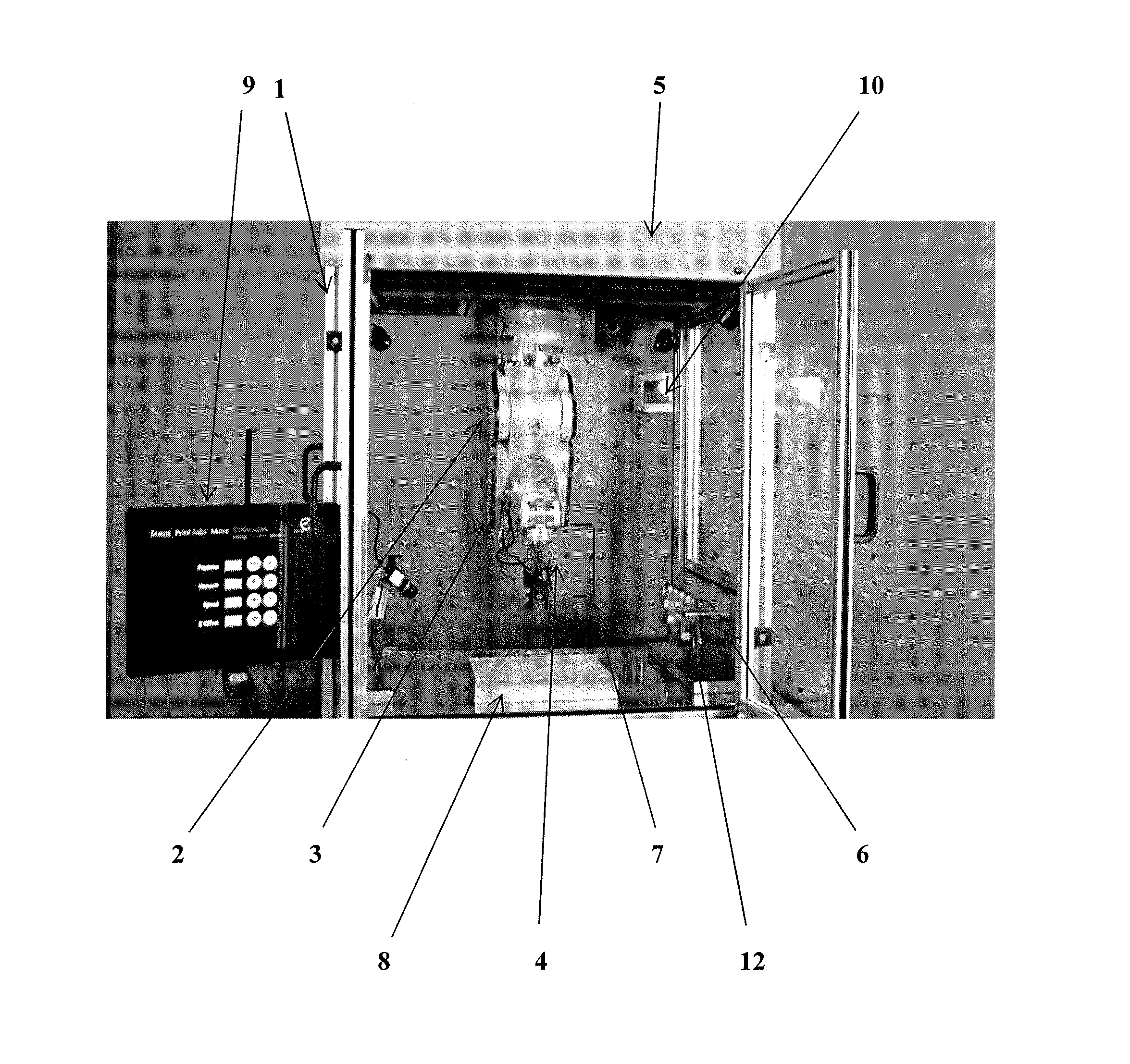
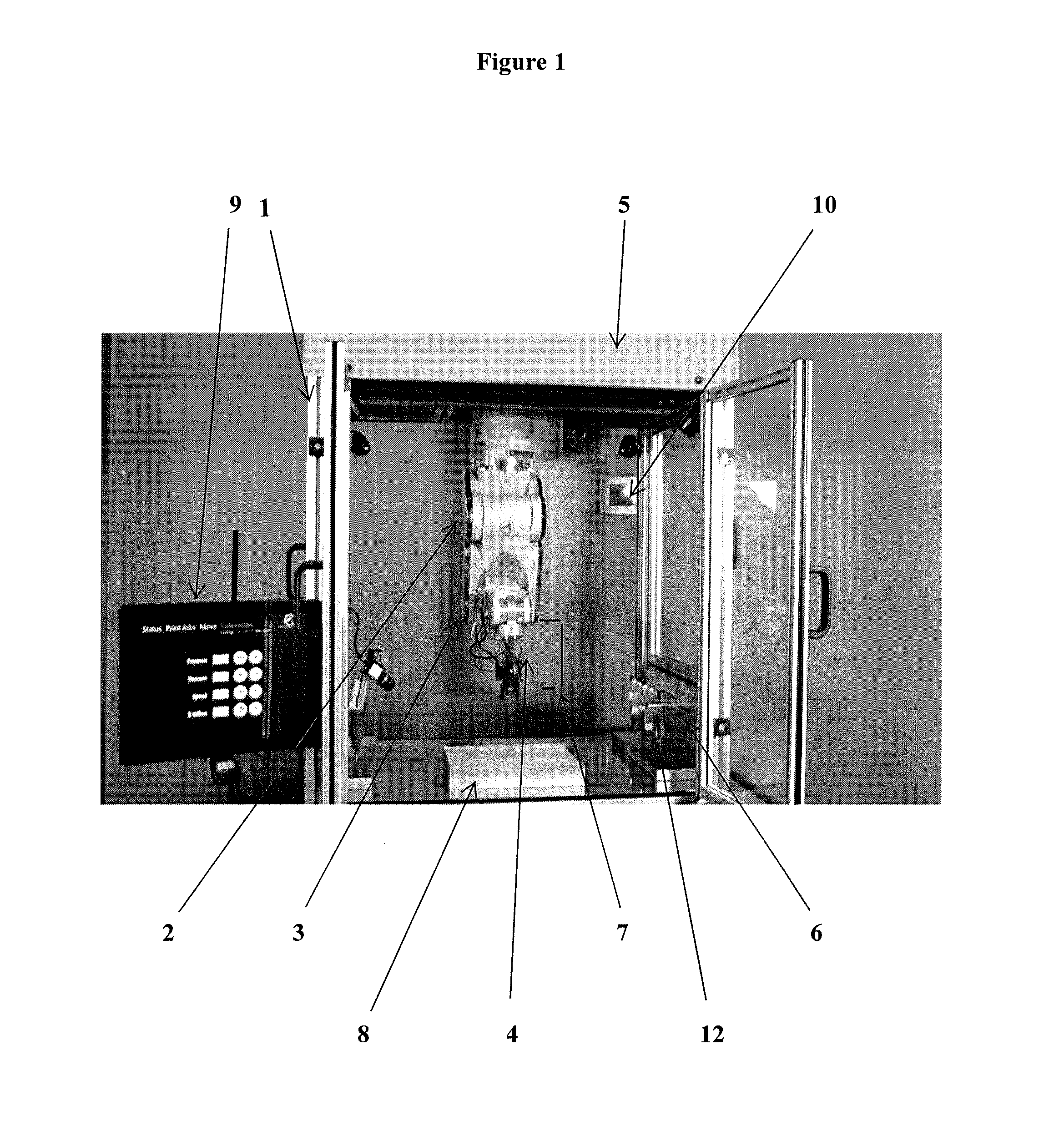
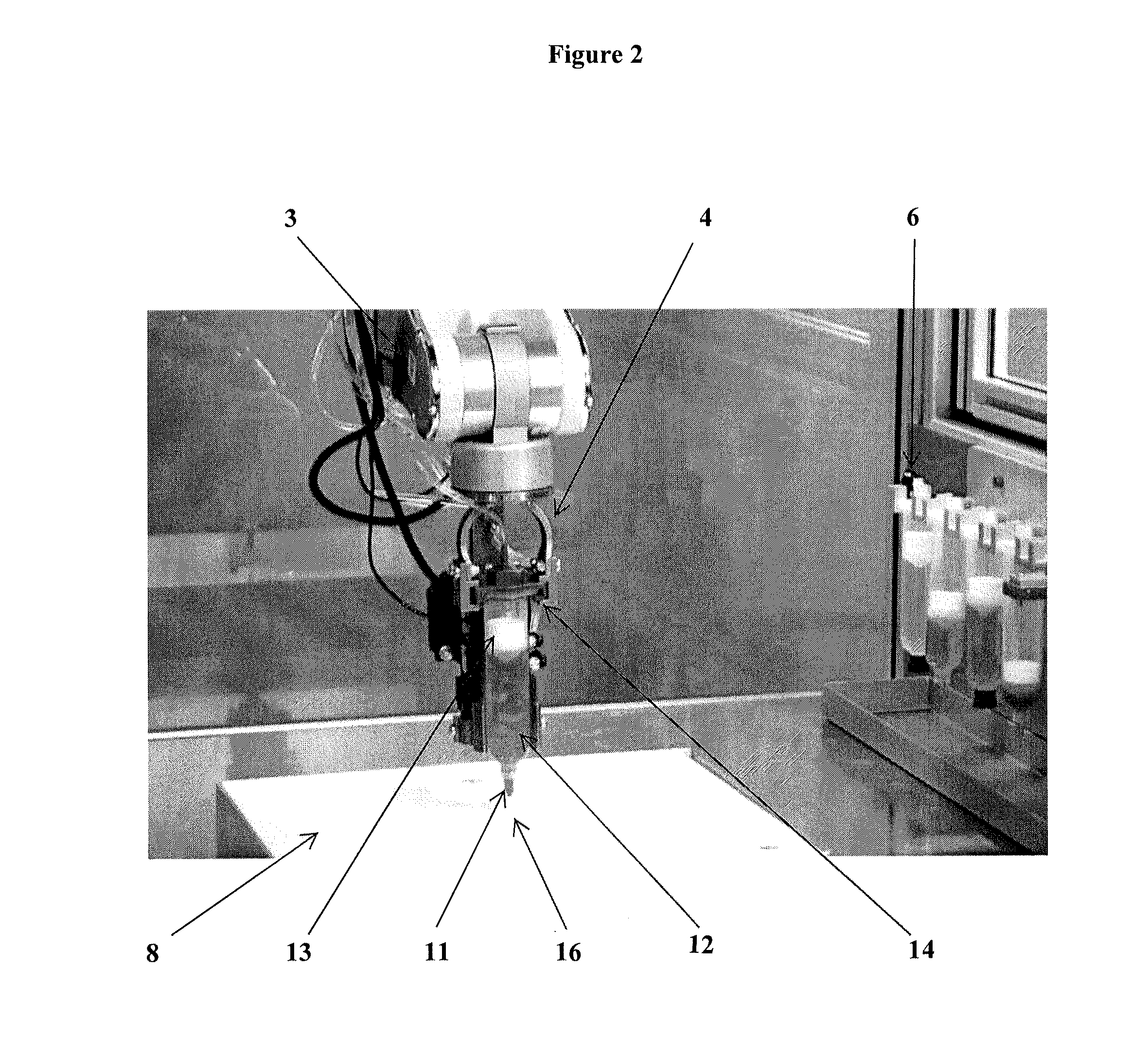
System and workstation for the design, fabrication and assembly of bio-material constructs
- Summary
- Abstract
- Description
- Claims
- Application Information
AI Technical Summary
Benefits of technology
Problems solved by technology
Method used
Image

Examples
example 1
[0159]This Example illustrates creation of simple objects in the object modeling environment.
[0160]A. Create a box (FIG. 7)[0161]1. Click on the Create a Box icon.[0162]2. Click the location on the modeling environment to begin placing the Box.[0163]3. The size of the Box's base can be adjusted by moving the mouse accordingly. To accept, click the left-mouse button to set the base.[0164]4. Moving the mouse vertically sets the height of the Box. To accept, click to set the height. Further refinements to the dimensions of the Box can be made by manually editing the center's coordinates or changing the length / depth / height of the Box.
[0165]B. Create a Sphere in the modeling environment (FIG. 8).[0166]1. Click on the Create a Sphere icon.[0167]2. Click the location in the modeling environment on which to place the sphere.[0168]3. The size of the sphere can be adjusted by moving the mouse. To set the size, click once more. The sphere may be further refined by manually entering the center'...
example 2
[0184]This Example illustrates manipulation of the objects in the object modeling environment. The objects added to the object modeling environment may be further manipulated, for example by combining, moving or aligning objects. In particular embodiments, objects may be combined to form unique / customized shapes. Operations for combining may include adding (union), subtracting (difference) and / or intersecting objects in the modeling environment.
[0185]A Union / Combine operation comprises merging together two separate object volumes so that their boundaries will be defined as a single region. A union operation is illustrated in FIG. 11.
[0186]A different operation is used to define a region boundary based on the subtraction of an actively selected object from an inactive object. A difference operation is illustrated in FIG. 12.
[0187]An interesection operation is used to define a region boundary based on the intersection of two objects. An intersection operation is illustrated in FIG. 13...
example 3
[0192]This Example illustrates importing objects directly into the modeling environment from other programs. Users may open existing model files created in external programs. Exemplary importable file formats include STL, NIfTI and DICOM.
[0193]Importing an STL file.[0194]1. Click on the Import STL icon in the Import section.[0195]2. Navigate to the folder containing the STL files.[0196]3. Highlight the desired file and click the ‘Open’ button to import the model.[0197]4. The object will appear in the modeling environment. As in the case of shapes created in TSIM, modification of the imported object is via the Objects menu on the right-hand side.
[0198]B. Importing a NIfTI file.[0199]1. Click on the Import NIfTI icon in the Import section.[0200]2. Navigate to the folder containing the NIfTI files[0201]3. Highlight the desired file and click the ‘Open’ button to import the model.[0202]4. The object will appear in the modeling environment. As in the case of shapes created in TSIM, modif...
PUM
| Property | Measurement | Unit |
|---|---|---|
| Time | aaaaa | aaaaa |
| Angle | aaaaa | aaaaa |
| Diameter | aaaaa | aaaaa |
Abstract
Description
Claims
Application Information