System and method for unified torque transmission and rotary sealing

Active Publication Date: 2015-04-23
GE GLOBAL SOURCING LLC
View PDF5 Cites 4 Cited by
  • Summary
  • Abstract
  • Description
  • Claims
  • Application Information

AI Technical Summary

Benefits of technology

[0008]In view of the above, it is desirable to provide a torque tube sealing arrangement in which cyclic precession is reduced. It is also desirab

Problems solved by technology

In particular, because the flinger is not mechanically fixed to the torque tube in the theta direction, it relies purely upon the friction generated by the interference fit and the clamp plates, bolts, and washers to keep it rotating in time with the torque tube.
However, the potential deformation of the torque tube has the effect of potentially manifesting a shear force in the flinger, causing it to rota

Method used


Image

  • System and method for unified torque transmission and rotary sealing
  • System and method for unified torque transmission and rotary sealing
  • System and method for unified torque transmission and rotary sealing

Examples


Example

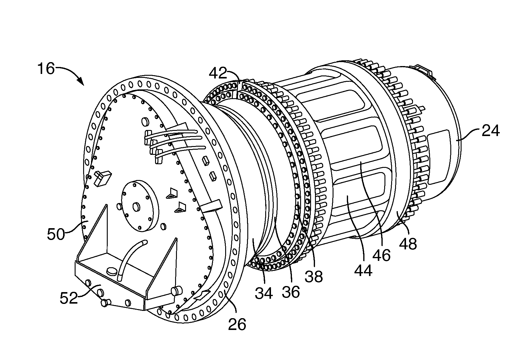
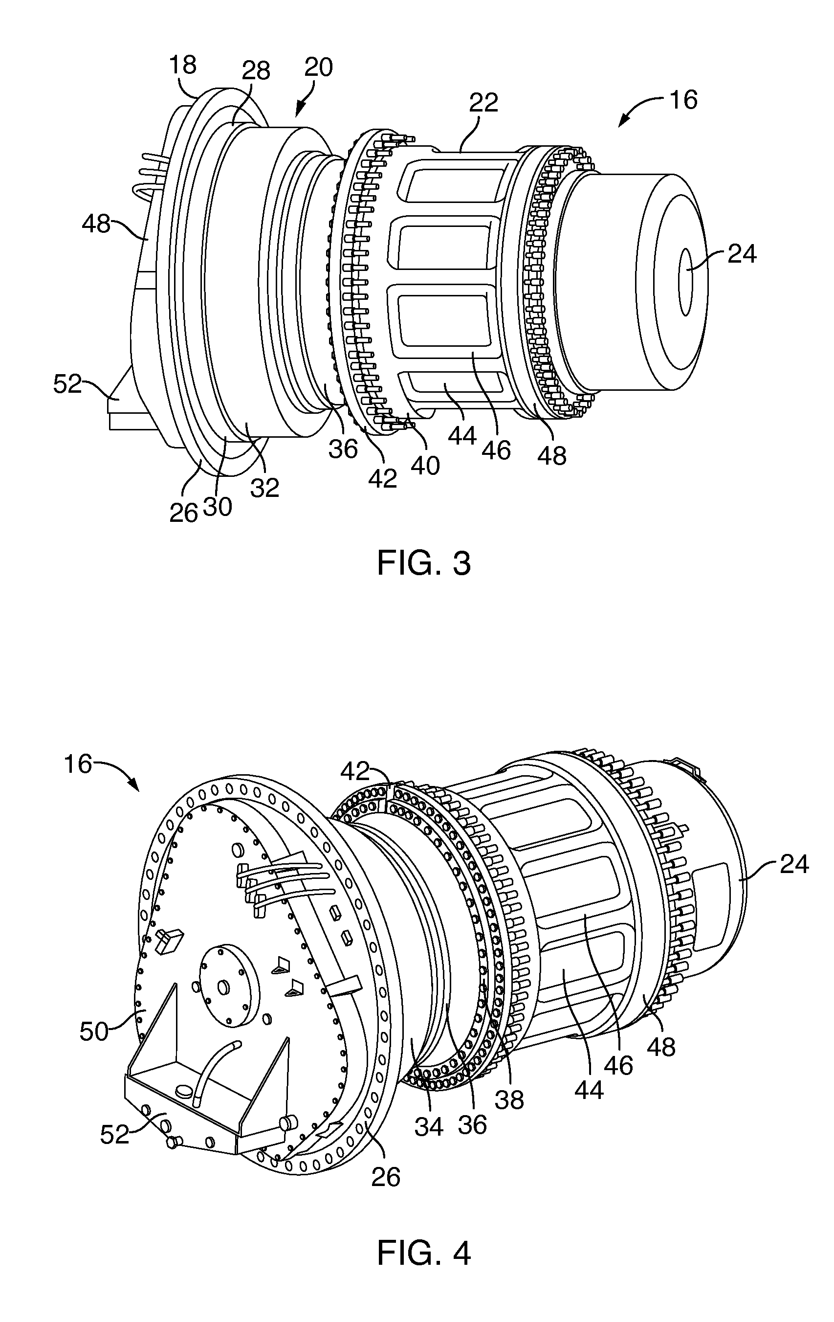
[0021]Reference will be made below in detail to exemplary embodiments of the invention, examples of which are illustrated in the accompanying drawings. Wherever possible, the same reference numerals used throughout the drawings refer to the same or like parts.

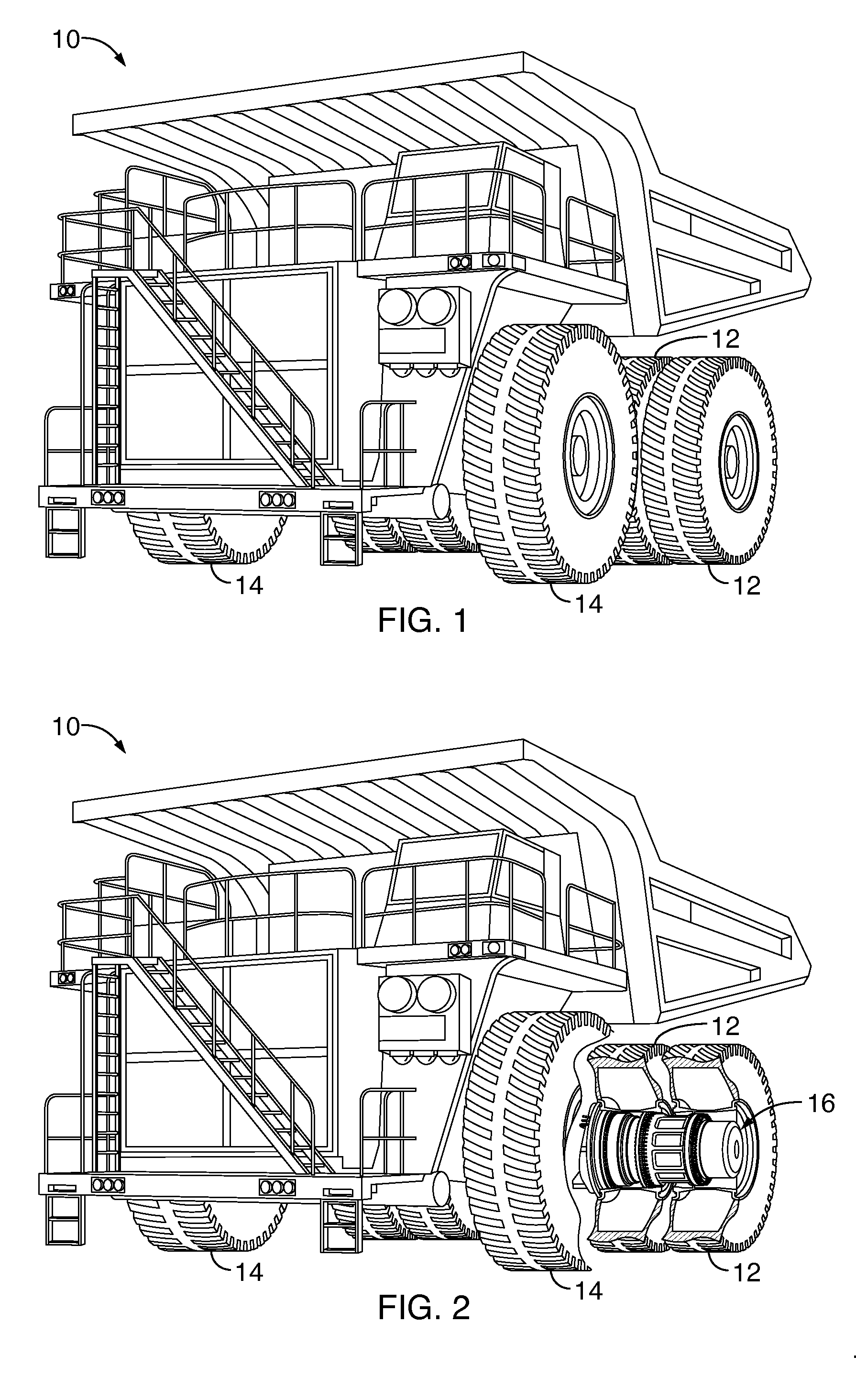
[0022]An embodiment of the inventive torque tube and sealing assembly 20 is configured for use with a wheel assembly 16 of an OHV 10 as depicted in FIGS. 1-5. As shown, the OHV 10 is supported on paired dual rear drive tire assemblies 12 and on single front steering tire assemblies 14. Each dual rear drive tire assembly 12 is mounted on a wheel drive assembly 16, which includes a wheel frame 18 as well as the torque tube 20 and a wheel hub 22 supported on the wheel frame and fastened to the torque tube 20. The tire assemblies 12 can be bolted to the wheel hub 22 as further discussed below. The wheel frame 18 also supports a brake assembly 24, which is disposed adjacent to an outboard end of the wheel hub 22 but is not fastened ...


PUM

PropertyMeasurementUnit
Lengthaaaaaaaaaa
Lengthaaaaaaaaaa
Lengthaaaaaaaaaa

Abstract

A torque transmission and sealing assembly includes a ring gear having a first axial end, a second axial end opposite the first axial end, an inner surface including a plurality of teeth and an axial-facing surface at the first axial end, a barrel portion joined to the second axial end of the ring gear, and a plurality of annular, axial extending fingers integrally formed with the ring gear and extending from the axial-facing surface.

Description

CROSS-REFERENCE TO RELATED APPLICATIONS[0001]This application claims priority to U.S. Provisional Application No. 61 / 892,598, filed Oct. 18, 2013.FIELD OF THE INVENTION[0002]Embodiments of the invention relate to wheel drive assemblies, and, more particularly, to wheel drive assemblies for off-highway vehicles.BACKGROUND OF THE INVENTION[0003]Off-highway vehicles (“OHVs”), such as mining vehicles used to haul heavy payloads, typically employ motorized wheels for propelling or retarding the vehicle in an energy efficient manner. This efficiency is typically accomplished by employing a large horsepower diesel engine in conjunction with an alternator, a main traction inverter, and a pair of wheel drive assemblies housed within the rear tires of the vehicle. The diesel engine drives the alternator and the alternator, in turn, powers the main traction inverter thereby supplying electrical power having a controlled voltage and frequency to electric drive motors of the wheel drive assembli...

Claims


Application Information

Patent Timeline
IPC IPC(8): B60K17/04
CPCB60K17/043B60K17/046B60B11/02B60B27/0026B60B27/0073B60K7/0007B60K2007/0038B60K2007/0092B60Y2200/142F16D1/101F16D2300/08Y10T29/49465Y10T74/19
Inventor TARBELL, GREGORYGIAMMARISE, ANTHONYPLUMMER, JEREMYVALLEJO, CARLOSOWENS, STEVENRICHTER, DENNISHECKER, GREGORY
Owner GE GLOBAL SOURCING LLC
Why Eureka
Try Eureka