
Amplified optical circuit

an optical circuit and amplifier technology, applied in the field of optical circuits, can solve the problems of attribution of a significant part of the cost of the optical circuit used for such ldvs, and the energy level of the reflected light received by the telescope, and achieve the effect of reducing the cost of certain types of optical circuits

Inactive Publication Date: 2015-04-23
SENSTHYS INC
View PDF12 Cites 42 Cited by
  • Summary
  • Abstract
  • Description
  • Claims
  • Application Information

AI Technical Summary

Benefits of technology

The patent text discusses the use of bidirectional amplifiers to reduce the cost of optical circuits used in environmental LDV applications. Bidirectional amplifiers are used to amplify light before it is transmitted out of a transceiver and again amplify the reflected light after it is received by the transceiver. This reduces the cost associated with certain optical circuits. The patent also mentions the use of multiplexing and passive or active switches to further reduce costs. Additionally, the patent discusses the use of polarization management to improve the performance of optical circuits used for LDV applications. By using non-polarization maintaining components and a passive polarization controller, the cost of the optical circuit can be significantly reduced while still maintaining acceptable performance.

Problems solved by technology

The energy level of the reflected light received by the telescope is quite low and has been identified as a cause of some drawbacks.
Thus, a significant part of the cost of the optical circuits used for such LDVs is attributed to the number of amplifiers used in the circuit.

Method used


Image

  • Amplified optical circuit
  • Amplified optical circuit
  • Amplified optical circuit

Examples


Embodiment Construction

[0044]The following detailed description is merely illustrative in nature and is not intended to limit the embodiments of the subject matter or the application and uses of such embodiments. As used herein, the word “exemplary” means “serving as an example, instance, or illustration.” Any implementation described herein as exemplary is not necessarily to be construed as preferred or advantageous over other implementations. Furthermore, there is no intention to be bound by any expressed or implied theory presented in the proceeding technical field, background, brief summary, or the following detailed description.

[0045]Certain terminology may be used in the following description for the purpose of reference only, and thus are not intended to be limiting. For example, terms such as “upstream”. “downstream”, “upper”, “lower”, “above”, and “below” refer to directions in the drawings to which reference is made. Terms such as “proximal”, “distal”, “front”, “back”, “rear”, and “side” describ...


PUM


Abstract

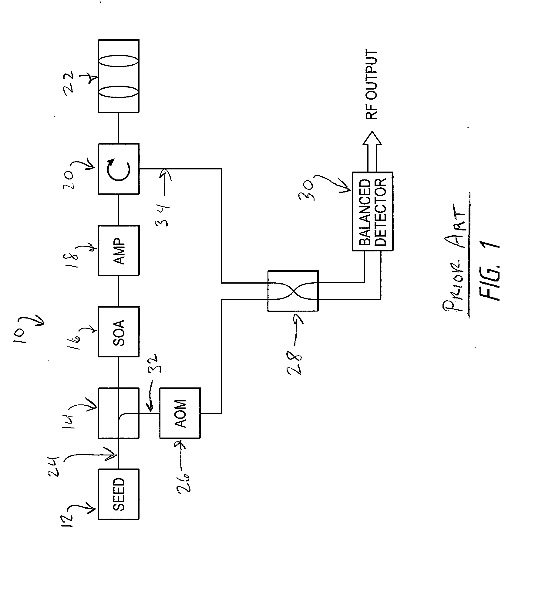
An optical circuit can include a bidirectional amplifier connected so as to amplify source light prior to emission through an output device such as a telescope as well as amplification of reflected light received by the telescope. Such an optical circuit can be used in laser doppler velocimeter applications as well as other applications. The optical circuit can also include passive splitters or active switches to provide for advantageous multiplexing.

Description

INCORPORATION BY REFERENCE TO ANY PRIORITY APPLICATIONS[0001]Any and all applications for which a foreign or domestic priority claim is identified in the Application Data Sheet as filed with the present application are hereby incorporated by reference under 37 CFR 1.57.BACKGROUND OF THE INVENTIONS[0002]1. Field of the Inventions[0003]Embodiments of the subject matter described herein relate generally to optical circuits which can include amplifiers and can be used as part of sensing apparatuses and for sensing methods such as Laser Imaging, Detection and Ranging (LIDAR) applications.[0004]2. Description of the Related Art[0005]Optical circuits are used in many different fields, including telecommunications and sensing technologies. In the telecommunications related technologies, light is primarily used as a carrier for digital communications. In such systems, the light remains contained within devices and circuitry which may be formed with integrated optical circuits, fiber optics, ...

Claims


Application Information

Patent Timeline
Patent Type & Authority Applications(United States)
IPC IPC(8): H01S3/067G01S17/58H04B10/00
CPCH01S3/06787G01S17/58H04B10/14G01S7/4811G01S7/4818G01S7/4868G01S7/499G01S17/95Y02A90/10
Inventor MAJOR, JR., JO STEPHENHOFLER, HANS JURGENGAISER, BRADLEY D.
Owner SENSTHYS INC
Learn More