
System and method for monitoring hydrogeological risk

a hydrogeological risk and system technology, applied in the direction of instruments, structural/machine measurement, excavation, etc., can solve the problems of high operating and implementation costs, difficult to obtain efficiency information, and high energy consumption, so as to reduce the cost of operation and implementation, the effect of reducing the time required

Pending Publication Date: 2021-09-30
OFFICINE MACCAFERRI SPA
View PDF1 Cites 6 Cited by
  • Summary
  • Abstract
  • Description
  • Claims
  • Application Information

AI Technical Summary

Benefits of technology

This patent describes a system that can monitor and alert about hydrogeological phenomena, such as rockfalls or changes in water levels. The device can detect mechanical stresses and displacements caused by the movement of debris flows. The system can also determine the exact location of the detected phenomenon, allowing for targeted interventions to prevent damage or minimize costs. Overall, this invention offers a more efficient and accurate way to monitor and manage hydrogeological risks.

Problems solved by technology

At present the known systems for monitoring and alerting are based on robust and heavy infrastructure in terms of sensors, data transmission and installation, with high operating and implementation costs, only accessible to the highly specialised world of geotechnics, geomechanics and geology.
For example, there are few specific experiences and cases for monitoring rockfall protection barriers, and those few known situations relate to systems with multiple sensors installed to verify the structure, such as inclinometers, strain gauges on the brakes of the structures, cameras and other devices with high energy consumption and difficulties in data transmission.
To date, it is therefore not easy to obtain information on the efficiency of rockfall protection barriers, for example if the structure has been impacted by a boulder, and thus its efficiency has been compromised.
From a usage point of view, the known systems are very limited because they require significant electricity resources to operate and expensive radio infrastructure, resulting in high costs in their installation and management, so as to prevent their use in many applications due to their inconvenience.
Often, where such systems are applied, they are in remote and inaccessible places, difficult to reach by man, not reached by the electricity grid and / or by telecommunications networks.
Furthermore, the optimal collection of information and / or hydrogeological risk alerts in real time is not always possible.
A drawback of the known monitoring systems is that it is not always possible to remotely carry out a control on the conditions of the protective devices such as rockfall protection nets, barriers, etc.
To date there is no simple and specific system that provides an alert in real time in the case of impact on the rockfall protection barrier or the single module of the barrier, nor in adhering nets and all the other applications.

Method used


Image

  • System and method for monitoring hydrogeological risk
  • System and method for monitoring hydrogeological risk
  • System and method for monitoring hydrogeological risk

Examples


Embodiment Construction

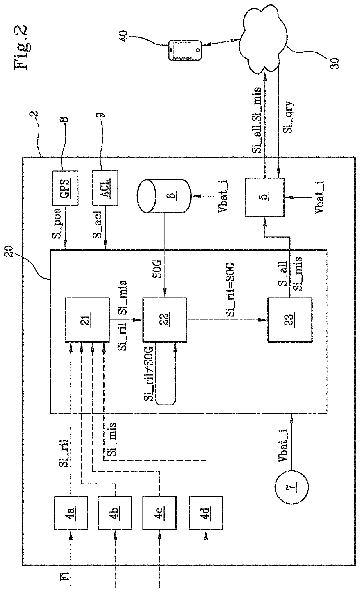
[0072]It should be observed that in the following description, identical or analogous blocks, components or modules are indicated in the figures with the same numerical references, even where they are illustrated in different embodiments of the invention.

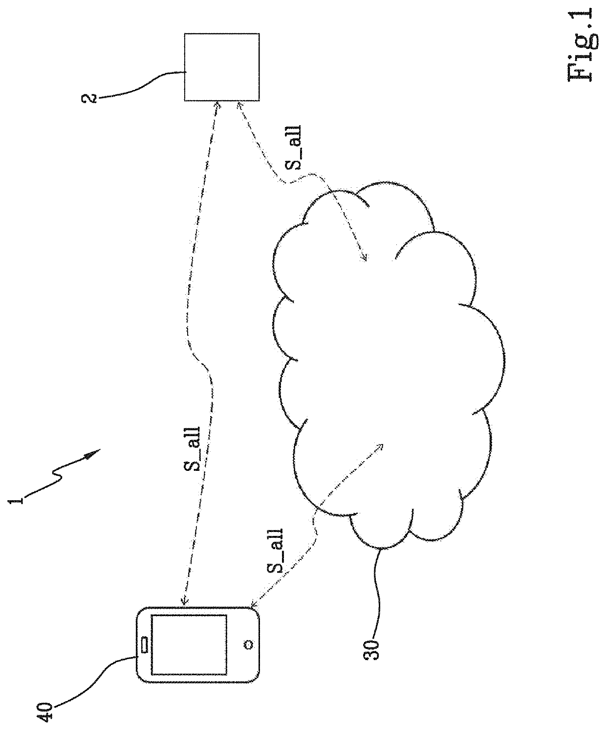
[0073]With reference to FIG. 1, the block diagram of the electronic system 1 for monitoring hydrogeological phenomena is shown.

[0074]The electronic system 1 for monitoring hydrogeological phenomena comprises:[0075]an electronic device 2 for monitoring hydrogeological phenomena;[0076]a wireless interactive electronic device 40;[0077]a telecommunications network 30.

[0078]The electronic device 2 for monitoring hydrogeological phenomena is fixed (for example by means of fixing clamps) to a control surface S or on the surface of a side or bank A near a torrential channel affected by the passage of a debris flow C1, C2, C3. The electronic device 2 can be, by means of non-limiting example, planted with a picket on the ground or on snow or ...


PUM

PropertyMeasurementUnit
sizeaaaaaaaaaa
sizeaaaaaaaaaa
voltage Vbataaaaaaaaaa

Abstract

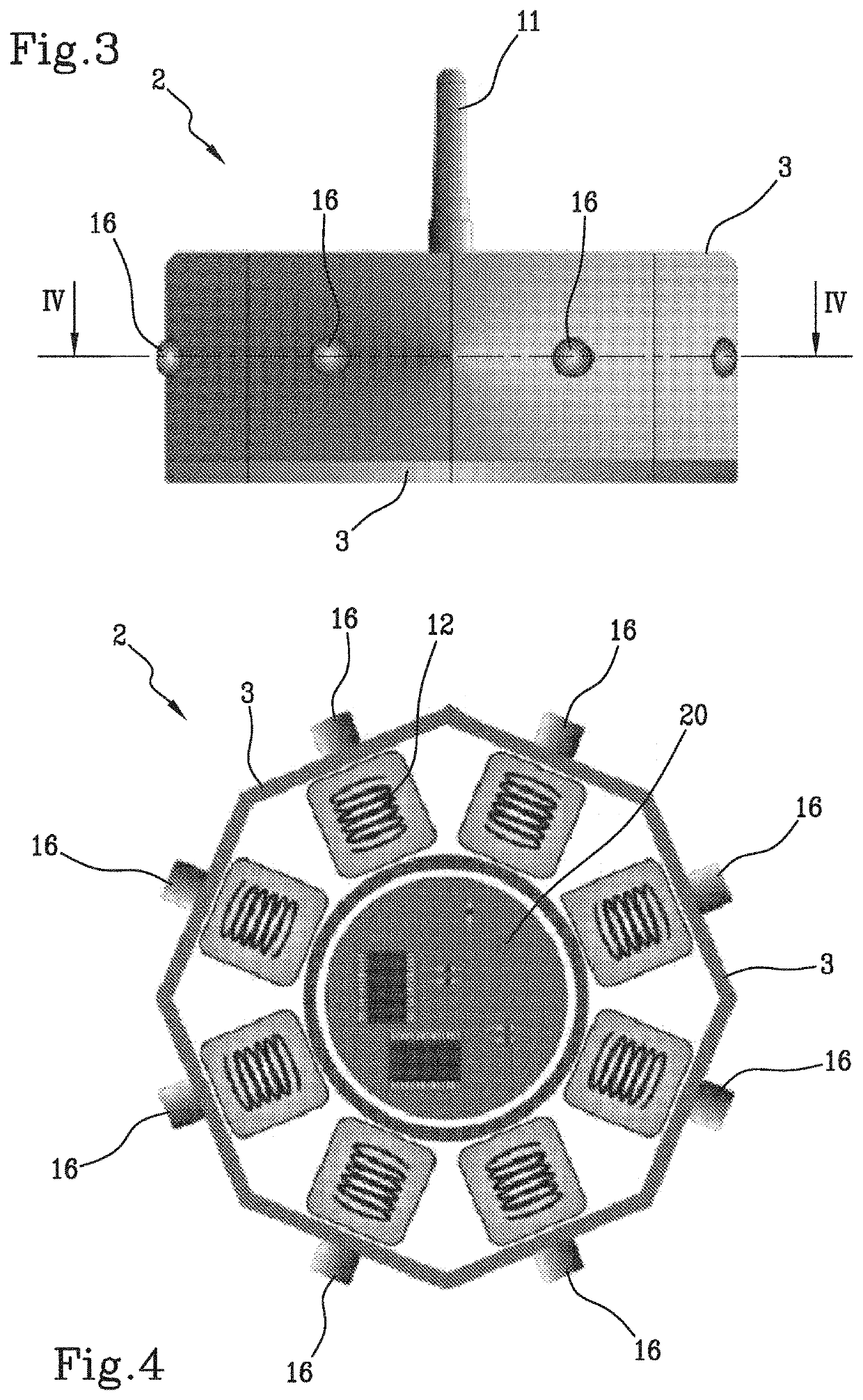
The present invention describes an electronic device (2) and corresponding method for monitoring hydrogeological phenomena, in particular the integrity of a rockfall protection barrier by detecting mechanical load exceeding a threshold, such as due to impact or debris flow. The device is provided with elongated flexible “legs” protruding from the housing in a radial manner and connected to a surface to be monitored (i.e. rockfall net) for detecting mechanical stress.

Description

TECHNICAL FIELD[0001]The present invention relates to an electronic and electromechanical device, a system and a method for monitoring and alerting of hydrogeological phenomena.[0002]In particular, the present invention relates to an electronic device, a system and a method for monitoring and alerting of hydrogeological phenomena acting on a rockfall protection barrier, a net, an adhering panel, a flexible debris barrier, a debris flow, a surface landslide, a snowslide, a bank or an embankment.[0003]In the discussion that follows the specific example of a single electronic and electromechanical device for monitoring hydrogeological phenomena will be considered. In particular, the present invention also relates to a plurality of electronic devices for monitoring hydrogeological phenomena in data communication with each other.[0004]Catchment basin is intended as the portion of land from which rain water or melting snow flowing on the surface collect in the same watercourse called a dr...

Claims


Application Information

Patent Timeline
Patent Type & Authority Applications(United States)
IPC IPC(8): G01M5/00G01L1/04G01L1/20G01L1/12G08B21/10
CPCG01M5/0041G01L1/046E01F7/045G01L1/127G08B21/10G01L1/20G01L1/26G08B25/009E01F7/04E02D17/202
Inventor ALBERTELLI, LUCA MAFFEOBASSETTO, PIERLUIGI
Owner OFFICINE MACCAFERRI SPA
Learn More