Secondary battery and electronic device

a technology of electronic devices and secondary batteries, applied in secondary cells, battery service/maintenance, cell components, etc., can solve the problem of limiting the time for operation of wearable devices, and achieve the effect of reducing the size of electronic devices, simple form, and efficient us

Active Publication Date: 2015-04-23
SEMICON ENERGY LAB CO LTD
View PDF5 Cites 59 Cited by
  • Summary
  • Abstract
  • Description
  • Claims
  • Application Information

AI Technical Summary

Benefits of technology

[0040]Part of a device like a watch is brought in contact with part of the body of a user, that is, the user wears the device, whereby the user can feel like the device is lighter than the actual weight. The use of a flexible secondary battery in an electronic device having a form with a curved surface that fits part of the body of a user allows the secondary battery to be fixed so as to have a form suitable to the electronic device and provided.
[0041]When a user moves part of the body on which an electronic device is worn, the user might feel uncomfortable, regard the electronic device as a distraction, and feel stress even in the case where the electronic device has a curved surface that fits part of the body. In the case where at least part of an electronic device can be changed in form according to movement of a body of a user, the user does not feel uncomfortable and a flexible battery can be provided in a portion of the electronic device that can be changed in form.
[0042]An electronic device does not necessarily have a form with a curved surface or a complicated form; an electronic device may have a simple form. For example, the number or size of components that can be incorporated in an electronic device with a simple form is determined depending on the volume of a space formed by a housing of the electronic device in many cases. Providing a flexible secondary battery in a small space between components other than the secondary battery enables a space formed by a housing of an electronic device to be efficiently used; thus, the electronic device can be reduced in size.

Problems solved by technology

Most wearable devices and portable information terminals include secondary batteries that can be repeatedly charged and discharged, and have problems in that there is a limitation on the time for operation of the wearable devices and the portable information terminals because their light weight and compactness limit the battery capacity.

Method used


Image

  • Secondary battery and electronic device
  • Secondary battery and electronic device
  • Secondary battery and electronic device

Examples


embodiment 1

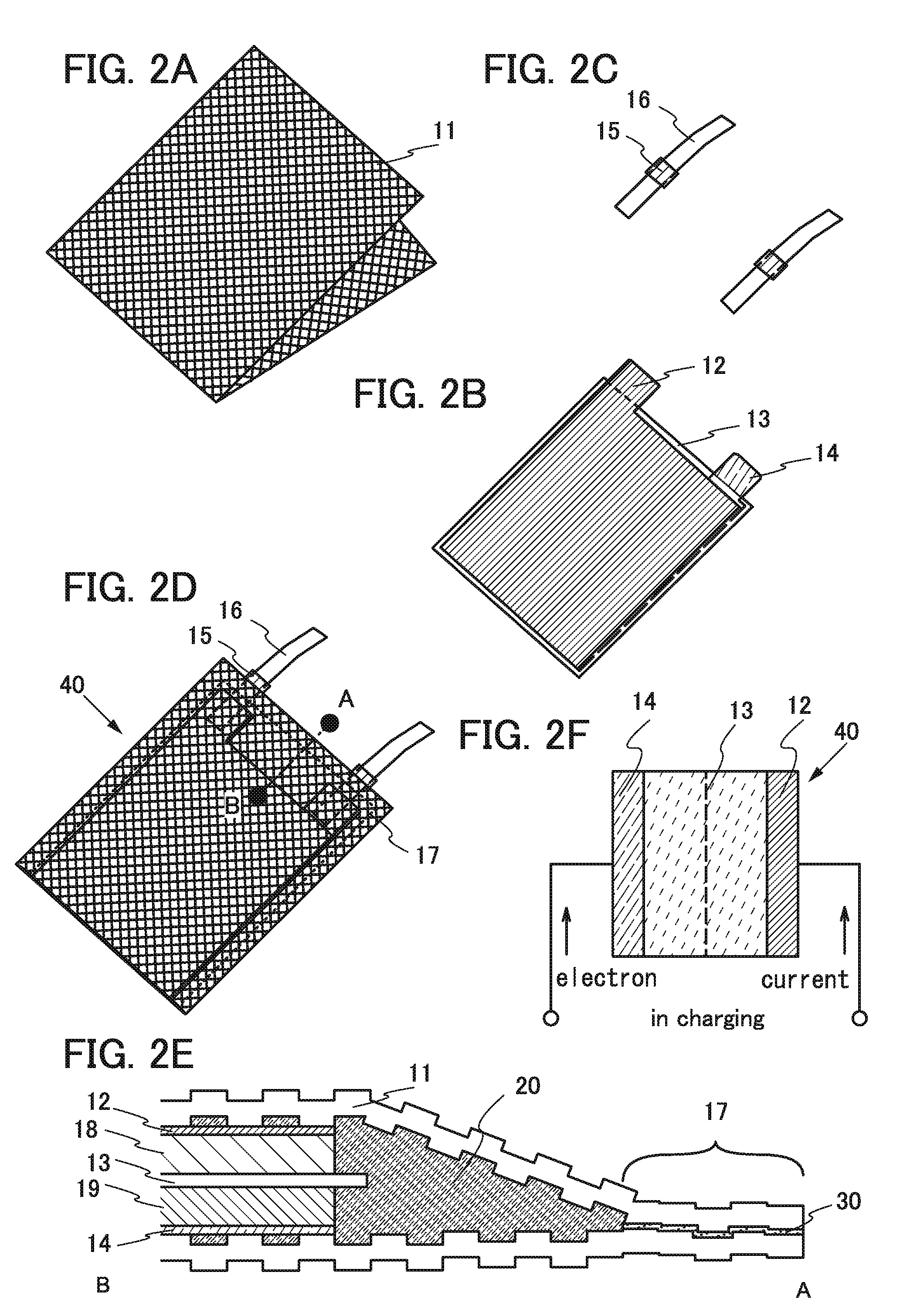
[0078]In this embodiment, an example of fabricating a lithium-ion secondary battery with the use of a film whose surface is embossed with a pattern will be described.

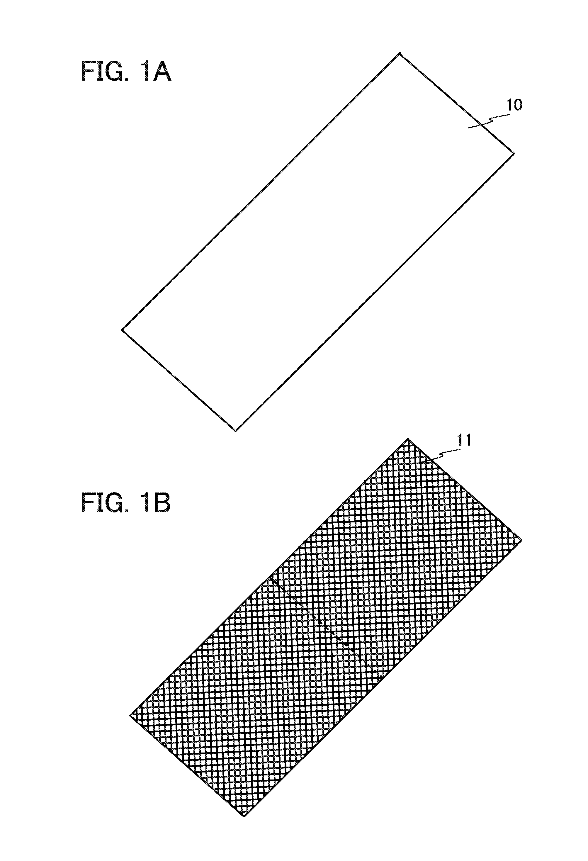
[0079]First, a sheet made of a flexible material is prepared. As the sheet, a stacked body, a metal film provided with an adhesive layer (also referred to as a heat-seal layer) or sandwiched between adhesive layers is used. As the adhesive layer, a heat-seal resin film containing, e.g., polypropylene or polyethylene is used. In this embodiment, a metal sheet, specifically, aluminum foil whose top surface is provided with a nylon resin and whose bottom surface is provided with a stack including an acid-proof polypropylene film and a polypropylene film is used as the sheet. This sheet is cut to obtain a film 10 illustrated in FIG. 1A.

[0080]Then, the film 10 is embossed to form unevenness so that the pattern can be visually recognized as illustrated in FIG. 1B. Although an example where the sheet is cut and then embossing ...

embodiment 2

[0129]In this embodiment, an example where a plurality of combinations of stacked layers that are partly different from those in Embodiment 1 is provided inside the folded film 11 will be described.

[0130]FIG. 4A is a top view of the positive electrode current collector 12. FIG. 4B is a top view of the negative electrode current collector 14. FIG. 4C is a top view of the separator 13. FIG. 4D is a top view of the lead electrode 16. FIG. 4E is a top view of the film 11.

[0131]The dimensions of the positive electrode current collector, the negative electrode current collector, and the separator are substantially the same in FIGS. 4A to 4C. A region 21 surrounded by a chain line in FIG. 4E has substantially the same dimensions as the separator in FIG. 4C. A region between a dotted line and an end face in FIG. 4E is the thermocompression-bonded region 17.

[0132]FIG. 5A is a perspective view of two combinations of pairs of a positive electrode and a negative electrode. Note that an example ...

embodiment 3

[0148]In this embodiment, an experiment where a secondary battery is fabricated and repetitively bent with a radius of curvature of 40 mm to 150 mm inclusive will be described. It is found that the repetitively bending the secondary battery with a radius of curvature of 40 mm to 150 mm inclusive causes no problem.

[0149]First, a secondary battery is fabricated using the embossed film 10 according to Embodiment 1.

[0150]In this embodiment, six combinations in each of which the positive electrode current collector 12, the separator 13, and the negative electrode current collector 14 are stacked as illustrated in FIG. 8A are used and wrapped with an exterior film. A positive electrode having one surface provided with a positive electrode active material layer and a negative electrode having one surface provided with a negative electrode active material layer are used. Specifically, the positive electrode having one surface provided with the positive electrode active material layer, the s...


PUM

PropertyMeasurementUnit
curvature radiusaaaaaaaaaa
angleaaaaaaaaaa
angleaaaaaaaaaa

Abstract

To provide a secondary battery that is suitable to a portable information terminal or a wearable device. To provide an electronic device having a novel structure that can have various forms and a secondary battery that fits the forms of the electronic device. The secondary battery includes a film provided with depressions or projections that can ease stress on the film due to application of external force. The sizes of the depressions or projections are different between a center portion and an end portion of the film. The end portion of the film is sealed with an adhesive layer. The depressions or projections of the film are formed by pressing such as embossing.

Description

BACKGROUND OF THE INVENTION[0001]1. Field of the Invention[0002]The present invention relates to an object, a method, or a manufacturing method. The present invention relates to a process, a machine, manufacture, or a composition of matter. One embodiment of the present invention relates to a semiconductor device, a display device, a light-emitting device, a power storage device, a driving method thereof, or a manufacturing method thereof. In particular, one embodiment of the present invention relates to an electronic device.[0003]Note that electronic devices in this specification mean all devices including secondary batteries, and electro-optical devices including secondary batteries, information terminal devices including secondary batteries, vehicles including secondary batteries, and the like are all electronic devices.[0004]2. Description of the Related Art[0005]In recent years, portable information terminals typified by smartphones have been actively developed. Portable inform...

Claims


Application Information

Patent Timeline
Patent Type & Authority Applications(United States)
IPC IPC(8): H01M10/04H01M2/14H01M50/105H01M50/119H01M50/121H01M50/124H01M50/133H01M50/466H01M50/533H01M50/55H01M50/557
CPCH01M10/0436H01M2220/30H01M2/14H01M4/70H01M50/557H01M50/46H01M50/105H01M50/55H01M50/121H01M50/133H01M50/124H01M50/533H01M50/119H01M50/466Y02E60/10H01M50/107H01M50/102H01M10/058H01M50/531H01M10/425H01M10/488H01M10/052
Inventor HIROKI, MASAAKIFURUMATSU, DAISUKE
Owner SEMICON ENERGY LAB CO LTD
Why Eureka
Try Eureka