Sensor device, force detecting device, robot, electronic component conveying apparatus, electronic component inspecting apparatus, and component machining apparatus

a technology of force detection and sensor device, which is applied in the direction of apparatus for force/torque/work measurement, programme control, instruments, etc., can solve the problems of wire rupture, conductive paste rupture (disconnection) by stress, and insufficient electrical connection of internal electrodes to wires, etc., to accurately detect external forces, properly perform work, and reduce the likelihood of connection failure

Active Publication Date: 2015-04-30
SEIKO EPSON CORP
View PDF20 Cites 25 Cited by
  • Summary
  • Abstract
  • Description
  • Claims
  • Application Information

AI Technical Summary

Benefits of technology

[0026]With this configuration, it is possible to obtain effects same as the effects of the force detecting device according to the application example 6. It is possible to feed back the external force detected by the force detecting device and more precisely execute work. Further, it is possible to detect, according to the external force detected by the force detecting device, for example, contact of the end effector with an obstacle. Therefore, it is possible to easily perform an obstacle avoiding operation, an obstacle damage avoiding operation, and the like, which are difficult in position control in the past, and more safely execute work.Application Example 8
[0032]With this configuration, it is possible to obtain effects same as the effects of the force detecting device according to the application example 6. By feeding back the external force detected by the force detecting device, the component machining apparatus can more precisely execute component machining work. Further, the component machining apparatus can detect, according to the external force detected by the force detecting device, for example, contact of the tool with an obstacle. Therefore, the component machining apparatus can immediately stop when an obstacle or the like comes into contact with the tool. The component machining apparatus can execute safer electronic component machining work.Application Example 11
[0038]With this configuration, it is possible to more surely protect the piezoelectric element. Further, for example, even if the piezoelectric element is deformed, it is possible to suitably prevent or suppress the wiring section from being ruptured and further reduce occurrence of a connection failure.Application Example 14
[0050]With this configuration, it is possible to provide the robot in which likelihood of occurrence of a connection failure is reduced. Therefore, with such a robot, it is possible to accurately detect an external force and properly perform work by the end effector.

Problems solved by technology

However, in the element of the force detecting device described in JP-A-2013-101020, since the internal electrodes are relatively thin, it is likely that the internal electrodes are not sufficiently electrically connected to the wire.
Further, it is likely that, when stress occurs, the conductive paste is ruptured (disconnected) by the stress.
Further, in the connection by the wire bonding in the force detecting device described in JP-A-2013-257267, in particular, when the copper wire and the like is soldered and joined, it is likely that the copper wire is ruptured (disconnected) by vibration or the like caused by an external force applied to the force detecting device to cause a connection failure.
Therefore, it is difficult to provide a sensor device, a force detecting device, a robot, an electronic component conveying apparatus, an electronic component inspecting apparatus, and a component machining apparatus having high reliability.

Method used


Image

  • Sensor device, force detecting device, robot, electronic component conveying apparatus, electronic component inspecting apparatus, and component machining apparatus
  • Sensor device, force detecting device, robot, electronic component conveying apparatus, electronic component inspecting apparatus, and component machining apparatus
  • Sensor device, force detecting device, robot, electronic component conveying apparatus, electronic component inspecting apparatus, and component machining apparatus

Examples


first embodiment

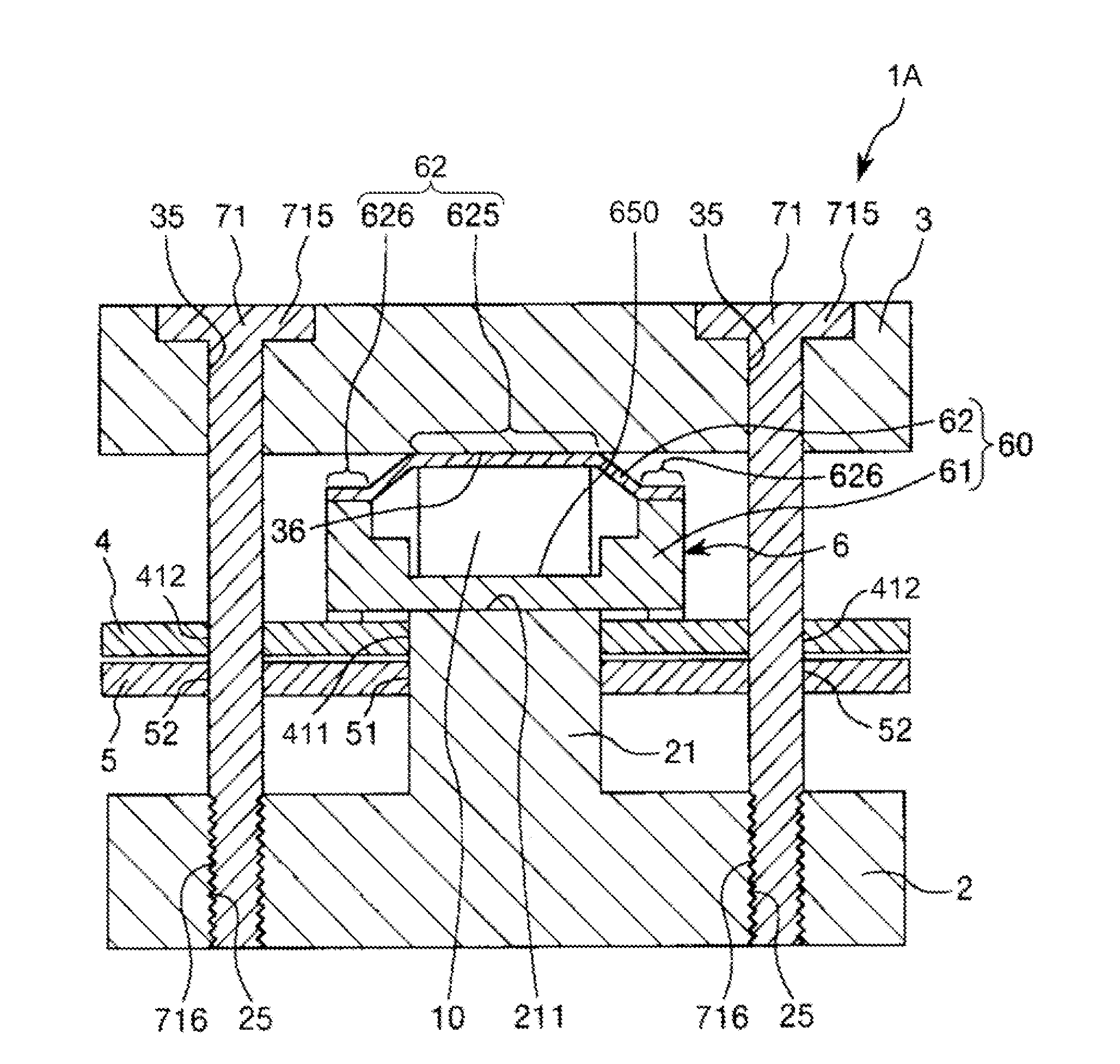
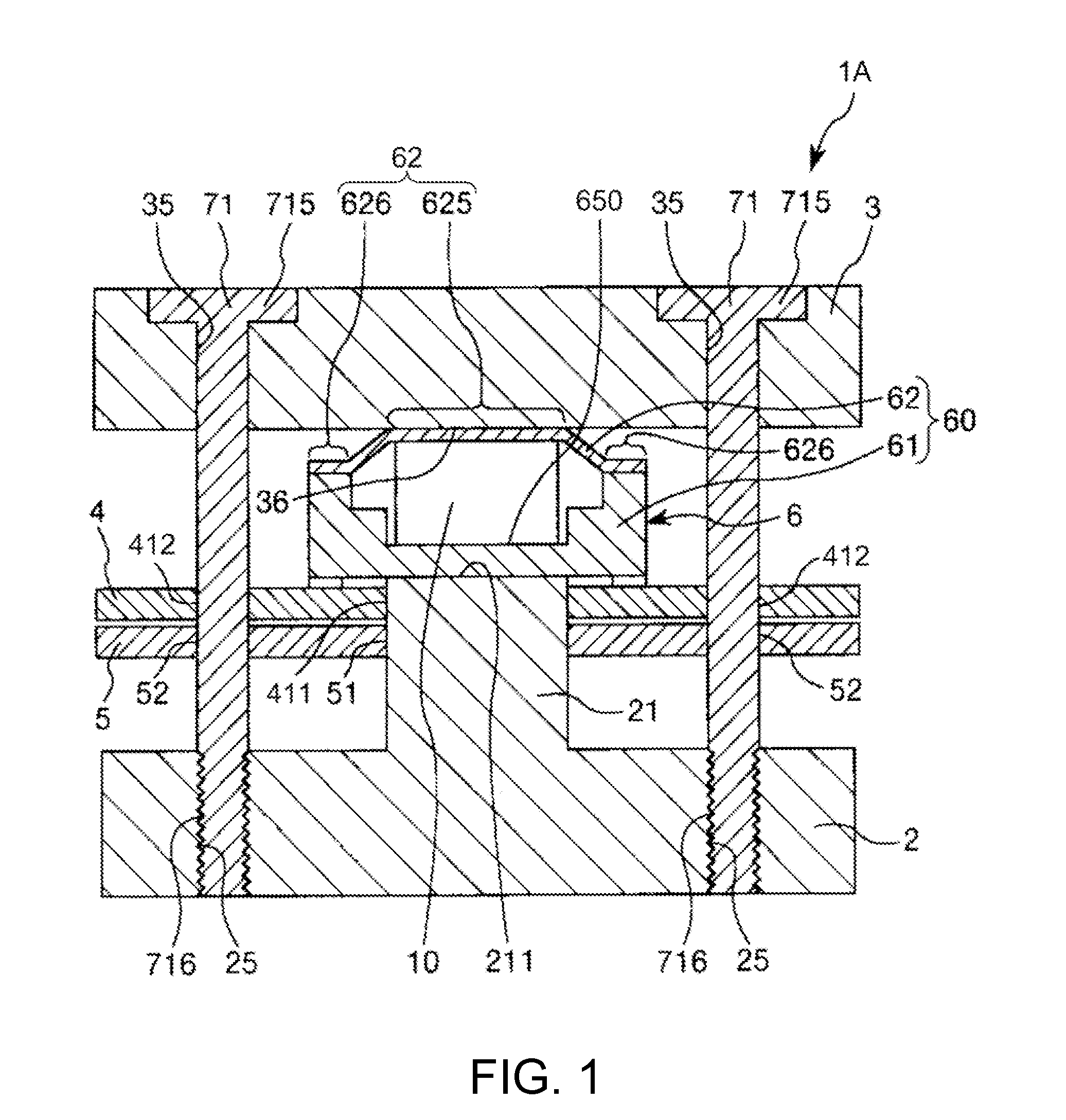
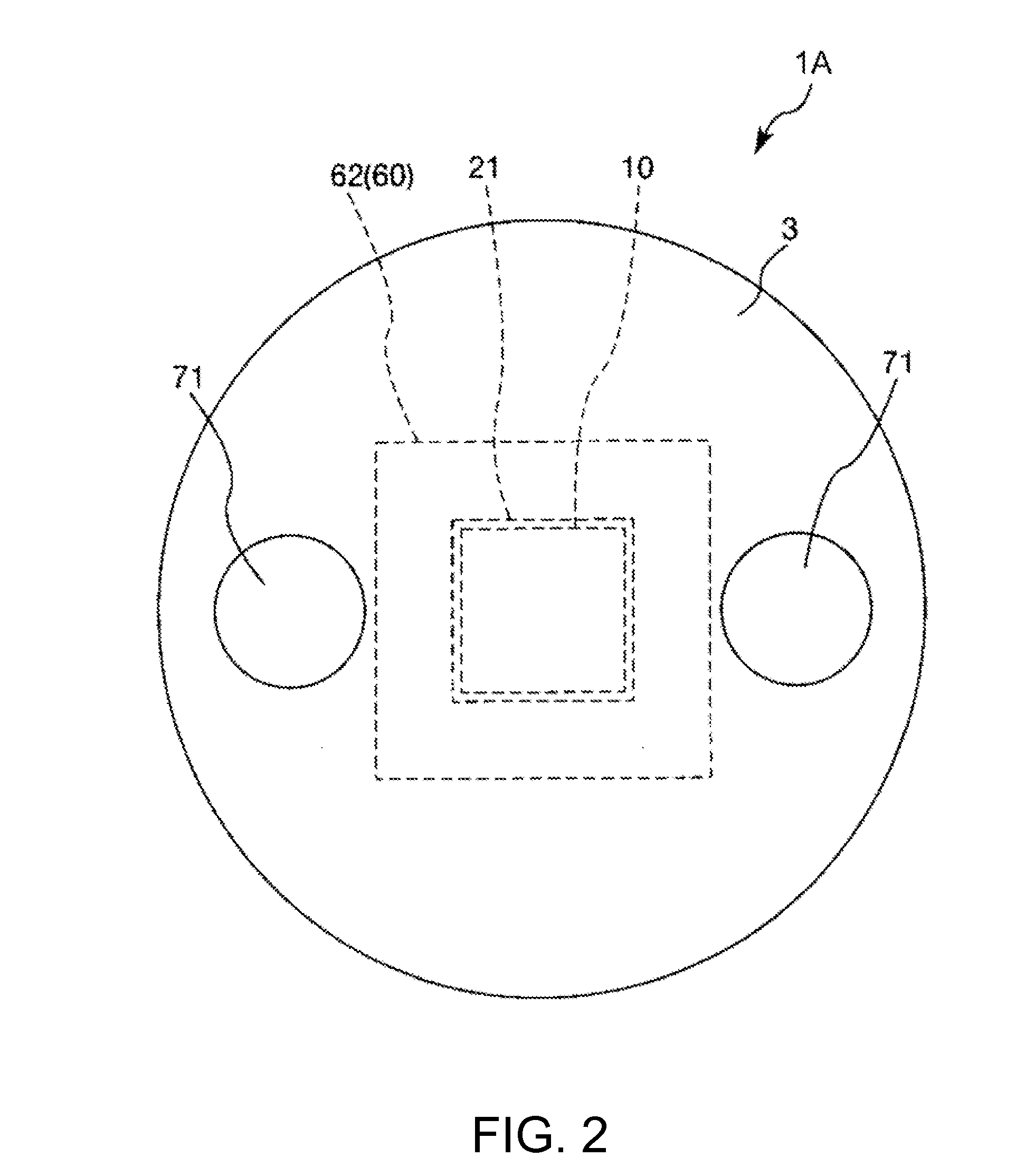
[0079]FIG. 1 is a sectional view showing a force detecting device (a sensor device) in a first embodiment of the invention. FIG. 2 is a plan view of the force detecting device shown in FIG. 1. FIG. 3 is a circuit diagram schematically showing the force detecting device shown in FIG. 1. FIG. 4 is a sectional view schematically showing a charge output element of the force detecting device shown in FIG. 1. FIGS. 5A and 5B are plan views showing an electrode layer of the charge output element shown in FIG. 1. FIGS. 6A and 6B are plan views showing the electrode layer and a ground electrode layer of the charge output element shown in FIG. 1, wherein FIG. 6A is a plan view showing the electrode layer and FIG. 6B is a plan view showing the ground layer. FIG. 7 is a sectional view showing the sensor device shown in FIG. 1. FIG. 8 is a diagram of the sensor device viewed from an arrow A1 direction in FIG. 7.

[0080]Note that, in the following explanation, for convenience of explanation, the up...

second embodiment

[0168]FIG. 9 is a plan view showing a force detecting device in a second embodiment of the invention. FIG. 10 is a sectional view taken along line G-G in FIG. 9. FIG. 11 is a circuit diagram schematically showing the force detecting device shown in FIG. 9.

[0169]Differences of the second embodiment from the first embodiment are mainly explained below. Explanation of similarities is omitted.

Overview of the Force Detecting Device

[0170]A force detecting device 1B in the second embodiment shown in FIGS. 9 and 10 has a function of detecting an external force (including a moment), that is, a function of detecting six axial forces (translational force components (shearing forces) in x, y, and z-axis directions and rotational force components (moments) about x, y, and z axes).

[0171]As shown in FIGS. 9 and 10, the force detecting device 1B includes four sensor devices 6 and four pressurizing bolts 71. The positions of the sensor devices 6 are not particularly limited. However, in this embodim...

third embodiment

[0186]FIG. 12 is a sectional view showing a force detecting device in a third embodiment of the invention. FIG. 13 is a plan view of the force detecting device shown in FIG. 12. FIG. 14 is a circuit diagram schematically showing the force detecting device shown in FIG. 12. FIG. 15 is a sectional view schematically showing a charge output element included in the force detecting device shown in FIG. 12. FIG. 16 is a schematic diagram showing an action state of a force detected by the charge output element of the force detecting device shown in FIG. 12. FIG. 17 is a diagram of the charge output element viewed from an arrow D direction in FIG. 16. FIG. 18 is a partially enlarged detailed view of the vicinity of the charge output element of the force detecting device shown in FIG. 12. FIG. 19 is a plan view of the charge output element shown in FIG. 18.

[0187]Note that, in the following explanation, the upper side in FIG. 12 is referred to as “up” or “upward” and the lower side in the fig...


PUM


Abstract

A sensor device includes a charge output element including a plurality of piezoelectric bodies and an internal electrode formed between the piezoelectric bodies, a package that houses the charge output element, first conductive paste electrically connected to a plurality of the internal electrodes, and second conductive paste that electrically connects the first conductive paste and an output terminal and has a modulus of elasticity lower than a modulus of elasticity of the first conductive paste. A Young's modulus of the first conductive paste is equal to or higher than 3.4 GPa and equal to or lower than 5.0 GPa and a Young's modulus of the second conductive paste is equal to or higher than 0.1 GPa and equal to or lower than 0.2 GPa.

Description

[0001]The entire disclosures of Japanese Patent Application Nos. 2013-226535, filed Oct. 31, 2013 and 2014-054501, filed Mar. 18, 2014 are expressly incorporated by reference herein.BACKGROUND[0002]1. Technical Field[0003]The present invention relates to a sensor device, a force detecting device, a robot, an electronic component conveying apparatus, an electronic component inspecting apparatus, and a component machining apparatus.[0004]2. Related Art[0005]In recent years, for the purpose of improvement of productivity, industrial robots have been introduced into production facilities such as factories. Such an industrial robot includes an arm movable in one axial direction or a plurality of axial directions and an end effector such as a hand, an instrument for component inspection, or an instrument for component conveyance attached to an arm distal end side. The industrial robot can execute component assembly work, component machining work, component manufacturing work, component co...

Claims


Application Information

Patent Timeline
Patent Type & Authority Applications(United States)
IPC IPC(8): H01L41/113B25J19/02H01L41/047
CPCH01L41/1132B25J19/028H01L41/0472G01L1/16B25J13/085G01L5/226H10N30/50H10N30/302
Inventor MATSUZAWA, AKIRAKAMIYA, TOSHIYUKIKAWAI, HIROKI
Owner SEIKO EPSON CORP
Why Eureka
Try Eureka