
System and method for determining vital sign information of a subject

a system and information technology, applied in the field of system and method for determining vital sign information of a subject, can solve the problems of limited respiratory movement, expensive thermal cameras, and only working thermal measurements, and achieve the effect of enhancing the functionality of a low-cost devi

Active Publication Date: 2015-05-07
KONINKLJIJKE PHILIPS NV
View PDF10 Cites 19 Cited by
  • Summary
  • Abstract
  • Description
  • Claims
  • Application Information

AI Technical Summary

Benefits of technology

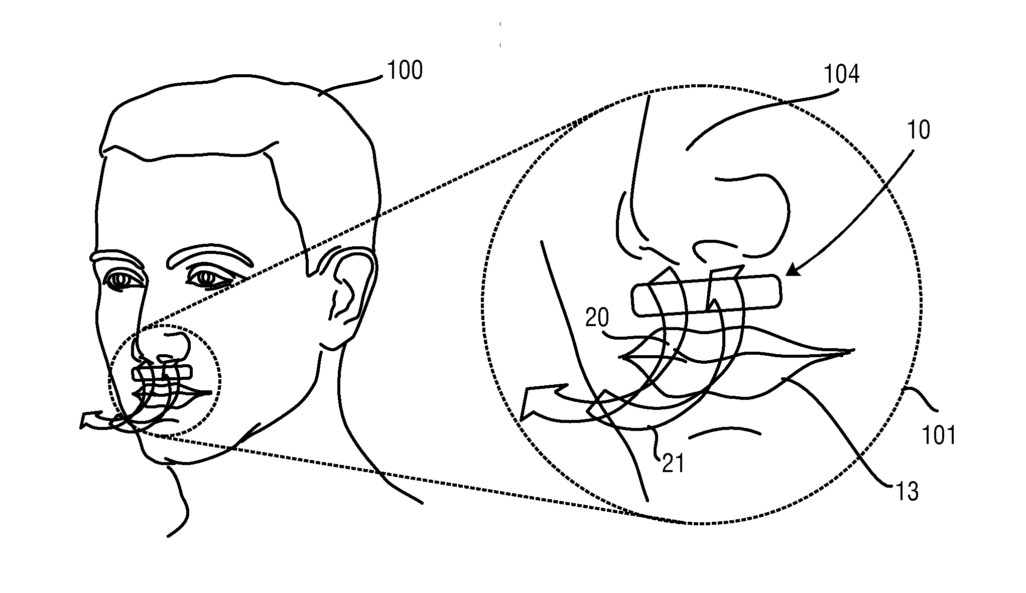
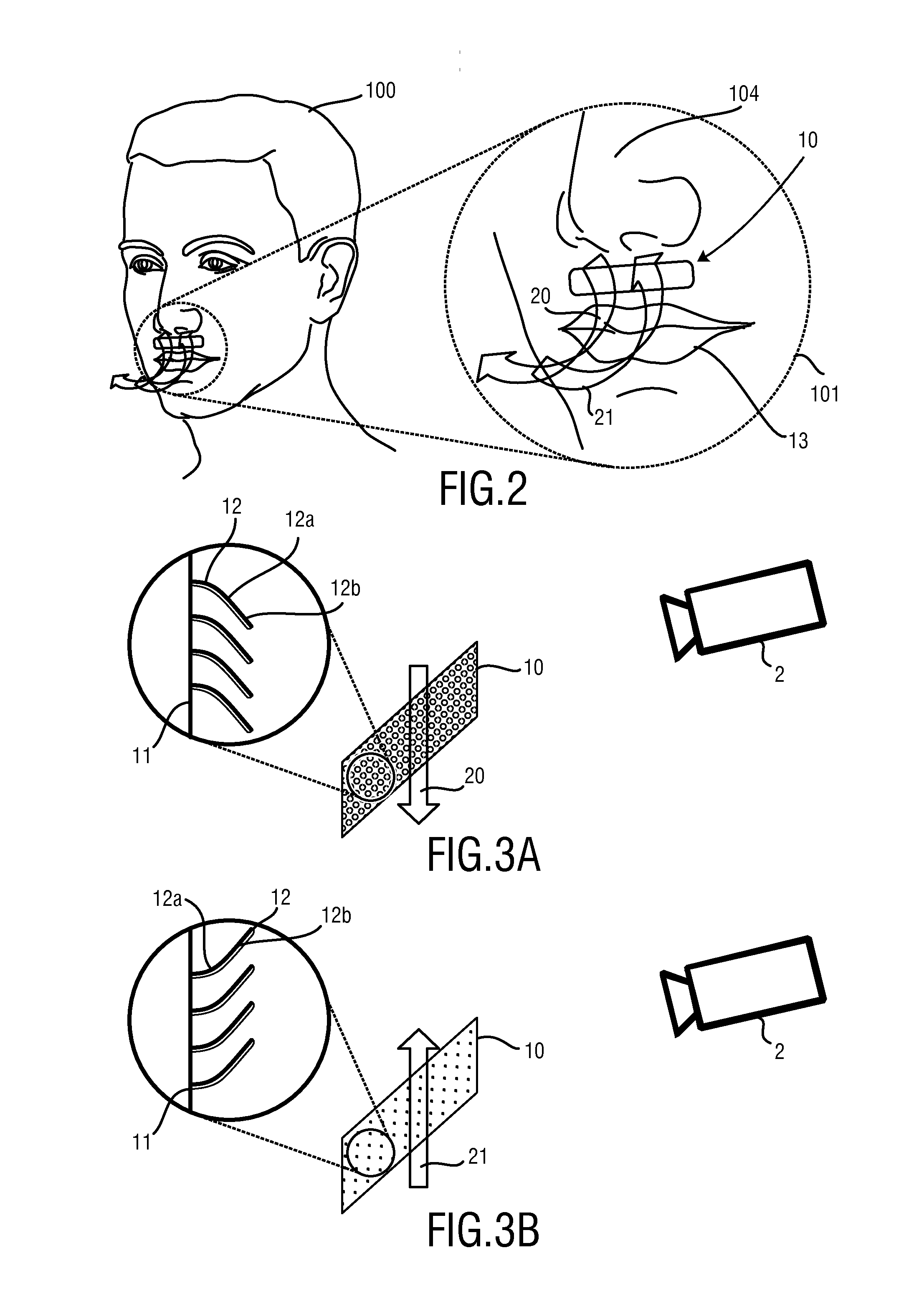
The present invention provides an improved system and method for unobtrusively and economically determining vital sign information of a subject. This is achieved by using a low-cost device that detects non-visible radiation, such as near infrared and / or near ultraviolet light, which is emitted by the body of the subject. The detection unit comprises an image sensor or camera, which is available at low cost, making the system more affordable and user-friendly. The invention allows for performing vital sign measurements in darkness without disturbing the patient at night and improves aesthetic appearance with the use of a marker that changes an optical property in the non-visible part of the spectrum. The technical effects of the invention revolve around enhancing the functionality of a low-cost device for determining vital sign information.

Problems solved by technology

A disadvantage of such systems is that a thermal measurement only works if there is a significant temperature difference between environmental temperature and exhaled air temperature.
A further disadvantage is that thermal cameras are expensive.
However, for example in a hospital setting where the patient is lying in bed and covered with a blanket, only a very limited respiratory movement can be observed.
Furthermore, a chest movement does not guarantee a gas flow into the lungs.
Furthermore, a motion-based respiration measurement is susceptible to motion artifacts.

Method used


Image

  • System and method for determining vital sign information of a subject
  • System and method for determining vital sign information of a subject
  • System and method for determining vital sign information of a subject

Examples


Embodiment Construction

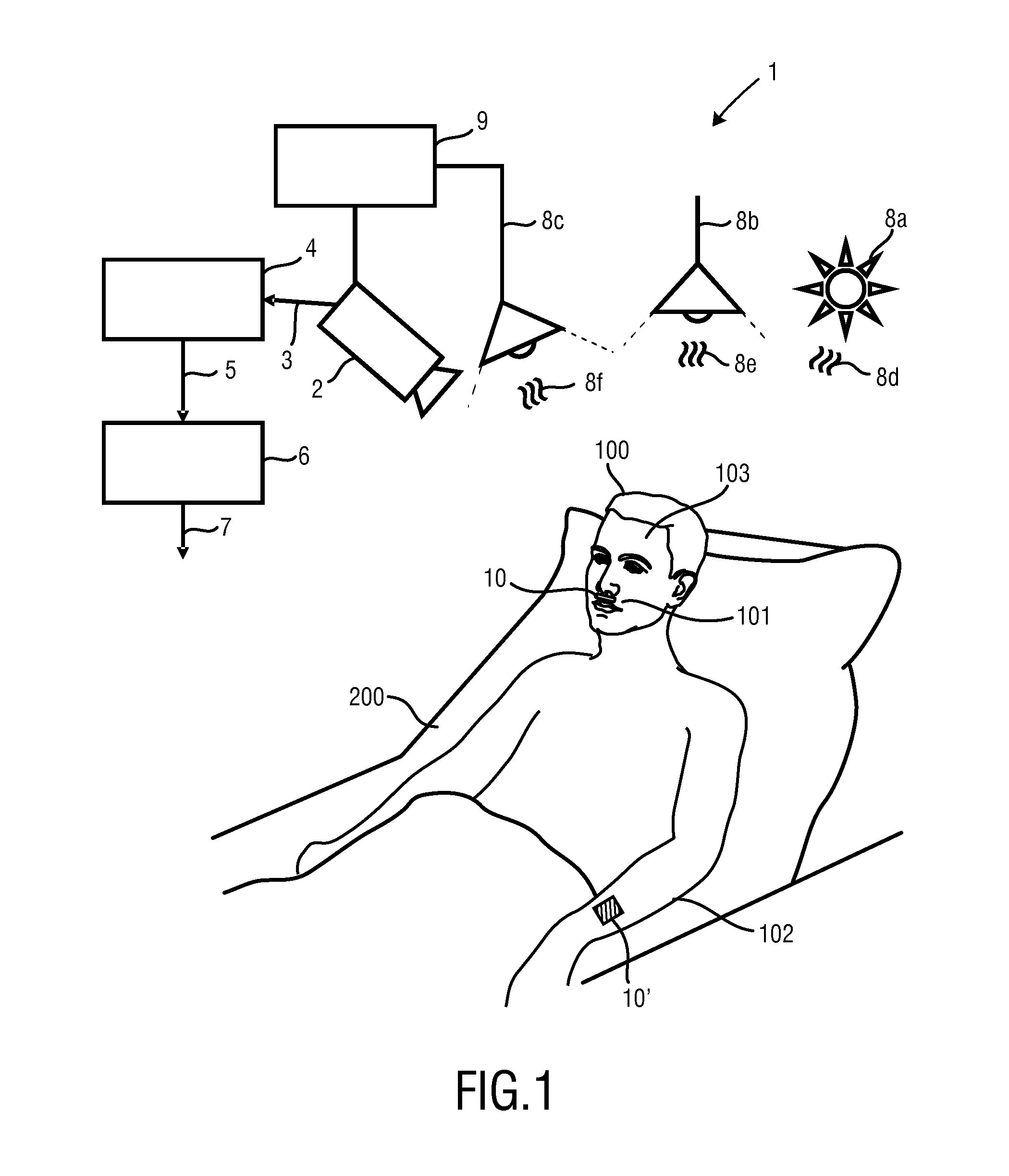
[0047]FIG. 1 shows an exemplary embodiment of a system 1 for determining vital sign information 7 of a subject 100 according to an aspect of the present invention. The system 1 comprises a marker 10 for application to the subject 100, a detection unit 2 and an analysis unit 6 as the basic components. In this example, the system 1 for determining vital sign information 7 of the subject 100 is employed in a clinical setting, where the subject 100 lies in bed 200.

[0048]The marker 10 is configured to change an optical property in response to a physiological process of the subject 100. In this example, the detection unit 2 is connected to an optional image processing unit 4. The detection unit 2 provides radiation data 3 that represents the detected radiation to the image processing unit 4 in form of a video stream. The image processing unit 4 identifies the marker 10 in the radiation data 3. The image processing unit 4 in turn is connected to the analysis unit 6. The image processing un...


PUM


Abstract

A system and method for determining vital sign information of a subject are presented. The system comprises a marker for application to the subject, wherein the marker is configured to change an optical property due to a mechanical manipulation of the marker caused by a physiological process of the subject, a detection unit for detecting radiation from the marker, and an analysis unit for determining the vital sign information of the subject from the detected radiation.

Description

CROSS REFERENCE TO RELATED APPLICATIONS[0001]This application claims the benefit of U.S. provisional application Ser. No. 61 / 898,554 filed Nov. 1, 2013 and EP provisional application serial no. 13191299 filed Nov. 1, 2013, both of which are incorporated herein by reference.FIELD OF THE INVENTION[0002]The present invention relates to a system and method for determining vital sign information of a subject, in particular to optical measurement for remotely determining vital signs of an observed subject.BACKGROUND OF THE INVENTION[0003]Vital signs of a subject, for example the heart rate (HR), the respiration rate (RR) or the body temperature serve as indicators of the current health status of a person and as powerful predictors of serious medical events. For this reason, vital signs are extensively monitored in in-patient and out-patient care settings, at home or in further health, leisure and fitness settings.[0004]US 2009 / 0204100 A1 discloses a body cover comprising a temperature sen...

Claims


Application Information

Patent Timeline
Patent Type & Authority Applications(United States)
IPC IPC(8): A61B5/087A61B19/00A61B5/091A61B5/00
CPCA61B5/0873A61B5/0077A61B19/54A61B5/091A61B5/6833A61B5/6819A61B2019/5479A61B5/0876A61B5/0075A61B5/7278A61B2019/5445A61B2019/5491A61B5/682A61B5/087A61B5/1114A61B5/1127A61B2090/3945A61B2090/3979A61B2090/3991A61B90/39G16Z99/00
Inventor DUBIELCZYK, ALEXANDEREPPING, CHRISTIAN MICHAELNEUMANN, ROLF
Owner KONINKLJIJKE PHILIPS NV
Learn More