Fixing device of electronic element

Inactive Publication Date: 2015-05-14
DELTA ELECTRONICS INC
View PDF1 Cites 7 Cited by
  • Summary
  • Abstract
  • Description
  • Claims
  • Application Information

AI Technical Summary

Benefits of technology

The invention is a new and simple fixing device for electronic elements. It has a main body with a guiding groove and a pressing portion for fixing the electronic element using a hook. As a result, the device can be easily assembled and disassembled with less force, increasing the lifespan of the device. The electronic element is placed inside the main body without needing to push or pull the hook, reducing the likelihood of damage to the hook.

Problems solved by technology

However, when the hook is pulled outwardly, the main body of the hook will undergo extremely large stress and is thus easily damaged or broken.
Currently, by precisely calculating the force balance among the hook, the container and the electronic element, the hook can be avoided from being damaged, but this brings limited effect.
In other words, the length of the main body of the hook needs to be changed according to the height of the electronic element, so the electronic element can not be fixed stably if the tolerance exists between the hook and the container.
That is to say, the structure of the conventional hook and container stands for little assembly tolerance and therefore the manufacturing cost will be increased.

Method used


Image

  • Fixing device of electronic element
  • Fixing device of electronic element
  • Fixing device of electronic element

Examples


Embodiment Construction

[0040]The present invention will be apparent from the following detailed description, which proceeds with reference to the accompanying drawings, wherein the same references relate to the same elements.

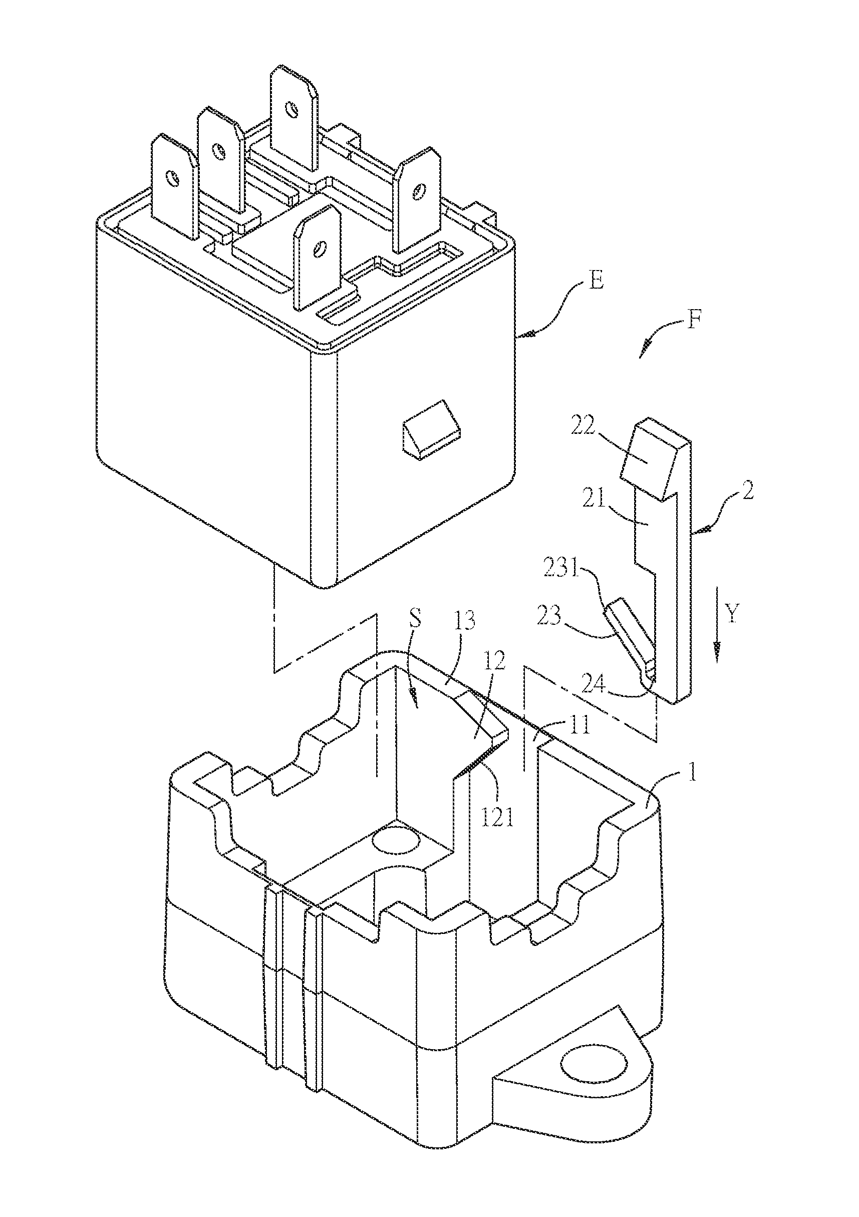
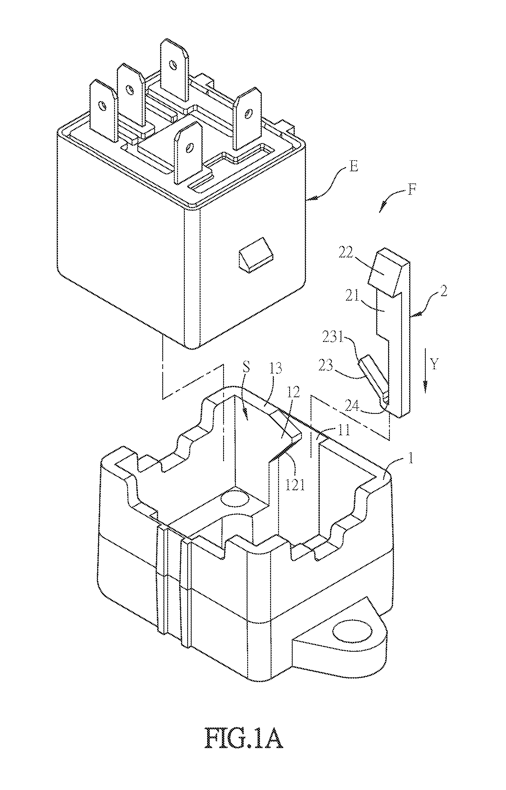
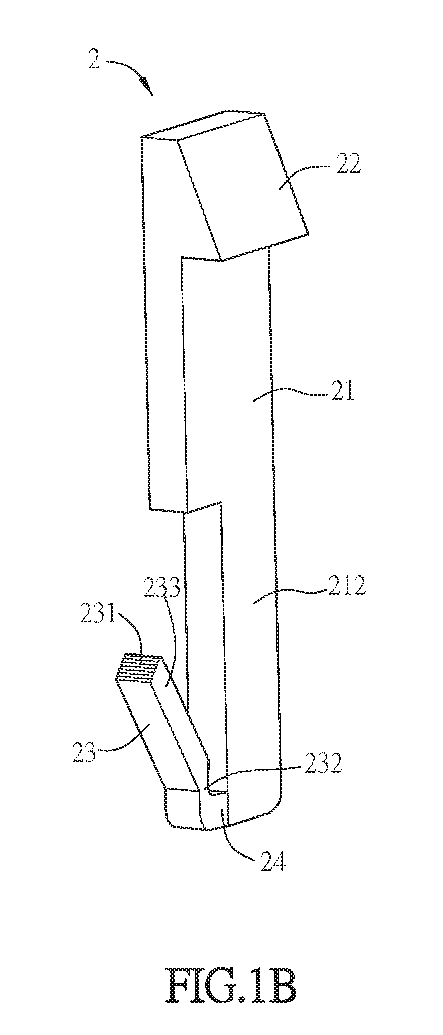
[0041]FIG. 1A is a schematic exploded diagram of a fixing device and an electronic element according to a first embodiment of the invention. As shown in FIG. 1A, the fixing device F of the electronic element E is used to fix the electronic element E and includes a main body 1 and a hook 2. The main body 1 has a space S for containing the electronic element E. The main body 1 further includes a guiding groove 11 and a block 12. The guiding groove 11 is disposed at a sidewall 13 of the space S. The hook 2 includes a body 21, a pressing portion 22, a cantilever 23 and a cushion structure 24. The pressing portion 22 is disposed on an end of the body 21 and the cushion structure 24 is connected to the other end of the body 21. In other words, the pressing portion 22 and the cushion structu...


PUM


Abstract

A fixing device of electronic element comprises a main body and a hook. The main body contains an electronic element and comprises a guiding groove and a block. The guiding groove is disposed at a sidewall of the main body. The block is disposed on a side of the guiding groove and has a blocking surface. The hook is disposed in the guiding groove to fix the electronic element and comprises a body, a pressing portion, a cantilever and a cushion structure. The pressing portion is disposed on one end of the body. The cantilever has a contact surface to press the blocking surface. Two ends of the cushion structure are connected to the other end of the body and the cantilever, respectively.

Description

CROSS REFERENCE TO RELATED APPLICATIONS[0001]This Non-provisional application claims priority under 35 U.S.C. §119(a) on Patent Application No(s). 102141131 filed in Taiwan, Republic of China on Nov. 12, 2013, the entire contents of which are hereby incorporated by reference.BACKGROUND OF THE INVENTION[0002]1. Field of Invention[0003]The invention relates to a fixing device and, in particular, to a fixing device for fixing electronic element.[0004]2. Related Art[0005]Generally, an electronic element is fixed by being disposed in a container including a hook disposed at and extended from the edge, and a protruding hook portion is formed on the top end of a main body of the hook. When the electronic element is disposed in the container, the main body can tightly contact the sidewall of the electronic element while the hook portion presses the top surface of the electronic element, and therefore the electronic element is fixed in the container.[0006]Because the container and the hook a...

Claims


Application Information

Patent Timeline
IPC IPC(8): H05K5/02
CPCH05K5/0247H05K5/0217H05K7/12
Inventor PAN, PO-LINSU, YUH-CHUWU, CHIA-CHI
Owner DELTA ELECTRONICS INC
Why Eureka
Try Eureka