Electronic device

Inactive Publication Date: 2015-05-21
SEMICON ENERGY LAB CO LTD
View PDF34 Cites 48 Cited by
  • Summary
  • Abstract
  • Description
  • Claims
  • Application Information

AI Technical Summary

Benefits of technology

[0010]In order that a user can comfortably wear a display device used while being worn on a human body, the display device needs to have light weight and

Problems solved by technology

Most wearable devices and portable information terminals include secondary batteries (also referred to as batteries) that can be repeatedly charged and discharged, and have problems in

Method used


Image

  • Electronic device
  • Electronic device
  • Electronic device

Examples


Example

Embodiment 1

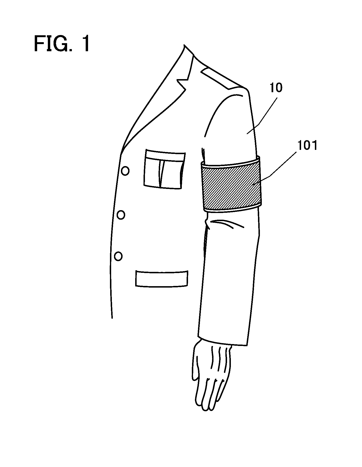
[0060]In this embodiment, an example of a novel device that can be worn on an upper arm will be described. FIG. 1 is a perspective view of the novel device that is worn on clothes.

[0061]As illustrated in FIG. 1, the novel device 101 is worn on a portion of clothes 10 that overlaps with a left upper arm. Examples of the clothes 10 include clothes with sleeves, such as a military uniform, an assault jacket, a suit jacket, a uniform, and space suits. There is no particular limitation on how to wear the novel device, and examples of ways to wear it include sewing it on a portion of clothes that overlaps with an upper arm, attaching it with a Velcro fastener (registered trademark) or the like provided on a portion of clothes that overlaps with an upper arm, fixing it with a band, a clasp, or the like, and winding a strip-like leaf spring around an upper arm.

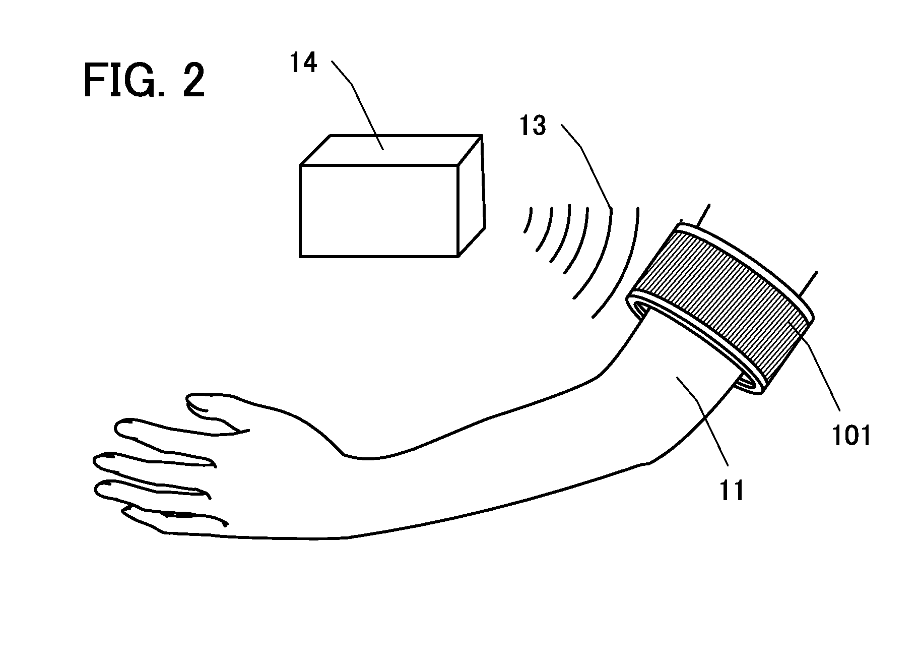
[0062]FIG. 2 is a perspective view illustrating the case where the novel device 101 is worn on a skin and wireless charg...

Example

Embodiment 2

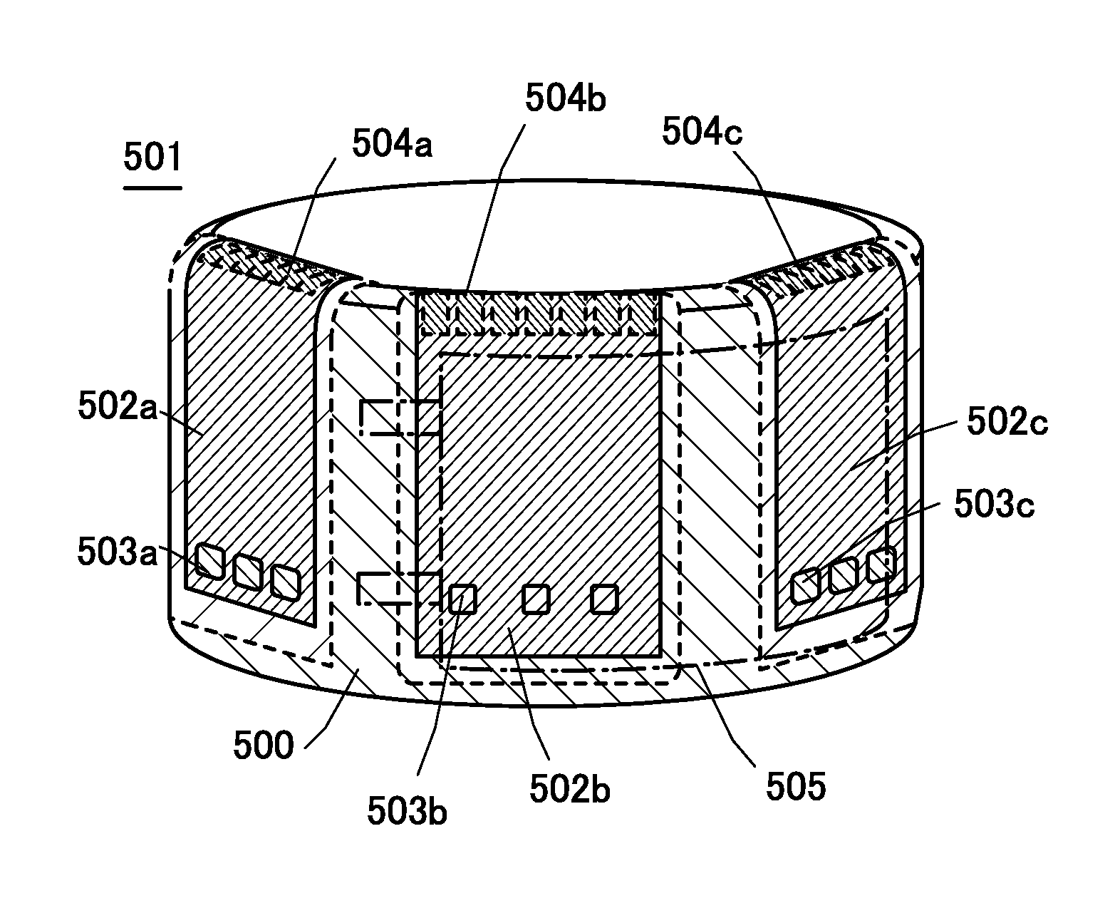
[0079]FIG. 5A illustrates an example of a novel device that is different from that of Embodiment 1. In this embodiment, a novel device 501 including a plurality of display panels will be described below.

[0080]The novel device 501 illustrated in FIG. 5A is provided with three display panels and includes a plurality of display regions. Display surfaces of the three display panels are different, which allows a user to view the display surface of any one of the display panels over a wide range from the side surface. In other words, a user can conveniently use the novel device 501 without moving the novel device 501 around part of his or her body and accurately fixing the position where the novel device is worn.

[0081]In the case where a user wears the novel device 501 illustrated in FIG. 5A on his or her upper arm, not only display regions 502a, 502b, and 502c on the side surface of the novel device 501 but also display regions 504a, 504b, and 504c on the top surface of the n...

Example

Embodiment 3

[0092]In this embodiment, an example of fabricating a flexible display panel by a separating method will be described. In this embodiment, an example of fabricating the flexible display panel using a separation layer will be described below.

[0093]First, a separation layer 203 is formed over a formation substrate 201, and a layer 205 to be separated (hereinafter referred to as a layer 205) is formed over the separation layer 203 (FIG. 8A). In addition, a separation layer 223 is formed over a formation substrate 221, and a layer 225 to be separated (hereinafter referred to as a layer 225) is formed over the separation layer 223 (FIG. 8B).

[0094]As the formation substrate 201, a substrate having at least heat resistance high enough to withstand process temperature in a manufacturing process is used. For example, a glass substrate, a quartz substrate, a sapphire substrate, a semiconductor substrate, a ceramic substrate, a metal substrate, a resin substrate, or a plastic subst...


PUM


Abstract

An arm-worn electronic device used while being worn on an arm is proposed. A novel device that includes a display portion having a curved surface, a secondary battery having a curved surface, and a member for being worn on a user's upper arm so that the display portion and the secondary battery are worn on the user's upper arm. Part of the display portion overlaps with the secondary battery. The novel device is useful for workers in the manufacturing industry and the distribution industry, police officers, fire fighters, health workers, care workers, sales people who work with their hands when it is worn on their arms. The novel device can also be used as military equipment or a wearable computer that assists a user who operates a vehicle or a plane, for the military's sake.

Description

BACKGROUND OF THE INVENTION[0001]1. Field of the Invention[0002]One embodiment of the present invention relates to a secondary battery and an electronic device including the secondary battery.[0003]Note that one embodiment of the present invention is not limited to the above technical field. The technical field of one embodiment of the invention disclosed in this specification and the like relates to an object, a method, or a manufacturing method. One embodiment of the present invention relates to a process, a machine, manufacture, or a composition of matter. Specific examples of the technical field of one embodiment of the present invention disclosed in this specification include a semiconductor device, a display device, a light-emitting device, a lighting device, a power storage device, a storage device, a method for driving any of them, and a method for manufacturing any of them.[0004]Note that electronic devices in this specification mean all devices including secondary batterie...

Claims


Application Information

Patent Timeline
IPC IPC(8): G06F1/16H02J7/02
CPCG06F1/163G06F1/1635H02J7/025G06F1/1605G06F1/1641G06F1/1652H02J50/20H02J7/00302H02J50/90H01M50/105H01M50/119H01M50/124H01M50/136H01M50/466
Inventor YAMAZAKI, SHUNPEI
Owner SEMICON ENERGY LAB CO LTD
Why Eureka
Try Eureka