Spintronic logic gates employing a giant spin hall effect (GSHE) magnetic tunnel junction (MTJ) element(s) for performing logic operations, and related systems and methods

a logic gate and hall effect technology, applied in pulse generators, pulse techniques, instruments, etc., can solve the problems of transistor-based logic gates that cannot operate at an appreciably faster speed, technique problems, and power consumption problems, so as to improve processing speed, simplify ic designs, and improve power efficiency

Inactive Publication Date: 2015-05-28
QUALCOMM INC
View PDF2 Cites 11 Cited by
  • Summary
  • Abstract
  • Description
  • Claims
  • Application Information

AI Technical Summary

Benefits of technology

[0010]Aspects described herein are related to spintronic logic gates employing a Giant Spin Hall Effect (GSHE) magnetic tunnel junction (MTJ) element(s) for performing logical operations. Related systems and methods are also disclosed. More specifically, this disclosure describes aspects of spintronic logic gates that include one or more GSHE MTJ elements configured to perform logical operations. Methods of performing logical operations using one or more GSHE MTJ elements are also disclosed. Additionally, related aspects and methods of fabricating GSHE MTJ elements are disclosed. Since logical operations are performed using GSHE MTJ elements, the spintronic logic gates and the methods for performing logical operations may provide for greater power efficiency than transistor-based logic gates. Also, the spintronic logic gates are capable of being disposed in a relatively compact arrangement within an integrated circuit (IC

Problems solved by technology

However, the MOS devices could not operate at an appreciably faster speed, because the mobility of the current mechanism (i.e., electrons or holes) did not also improve linearly, since mobility is a function of the effective mass of the current mechanism, and the effective mass was not changed w

Method used


Image

  • Spintronic logic gates employing a giant spin hall effect (GSHE) magnetic tunnel junction (MTJ) element(s) for performing logic operations, and related systems and methods
  • Spintronic logic gates employing a giant spin hall effect (GSHE) magnetic tunnel junction (MTJ) element(s) for performing logic operations, and related systems and methods
  • Spintronic logic gates employing a giant spin hall effect (GSHE) magnetic tunnel junction (MTJ) element(s) for performing logic operations, and related systems and methods

Examples


Embodiment Construction

[0040]With reference now to the drawing figures, several exemplary aspects of the present disclosure are described. The word “exemplary” is used herein to mean “serving as an example, instance, or illustration.” Any aspect described herein as “exemplary” is not necessarily to be construed as preferred or advantageous over other aspects.

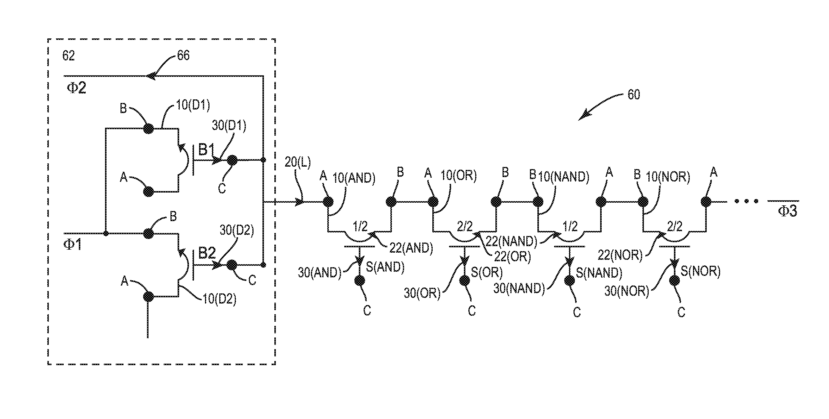
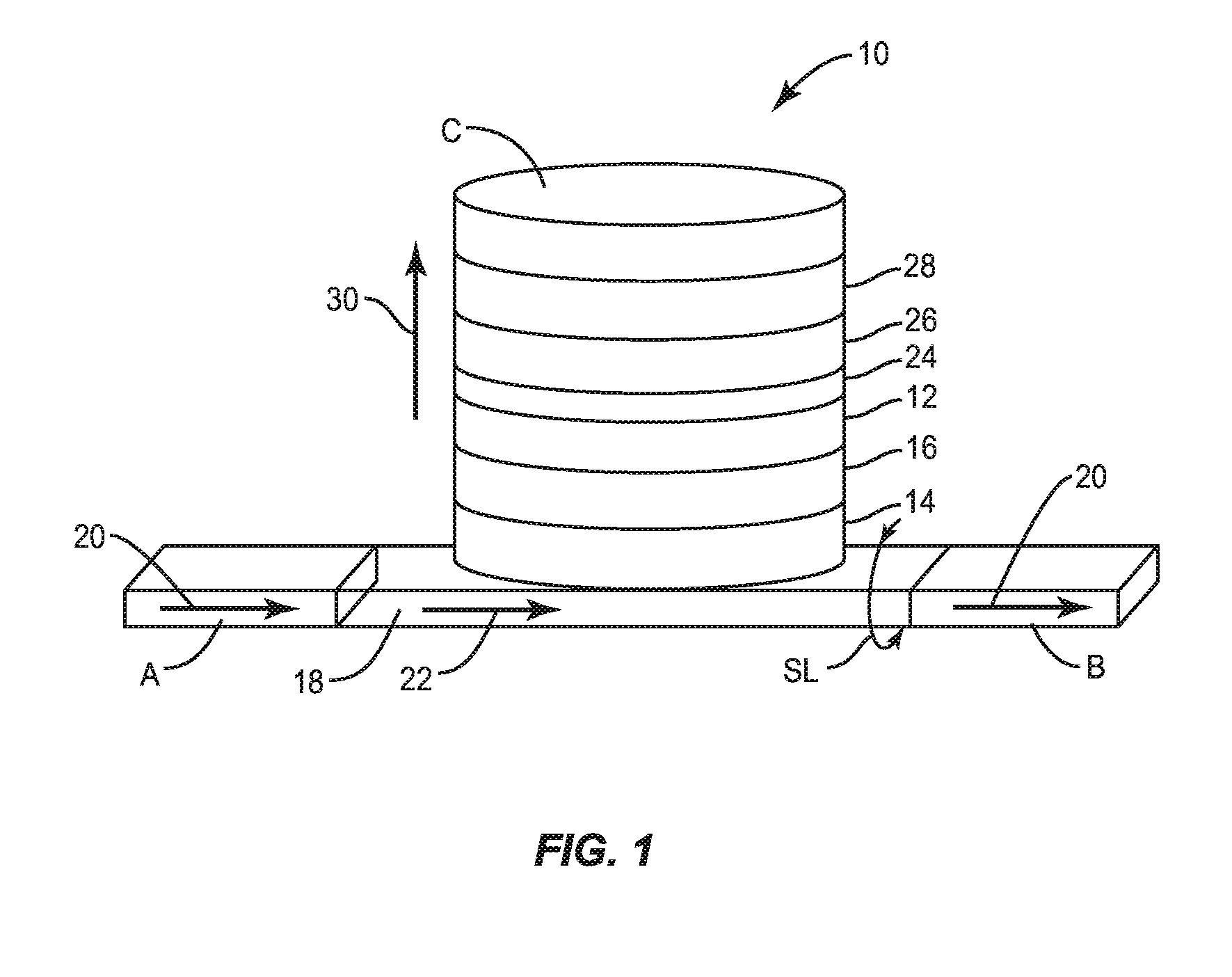
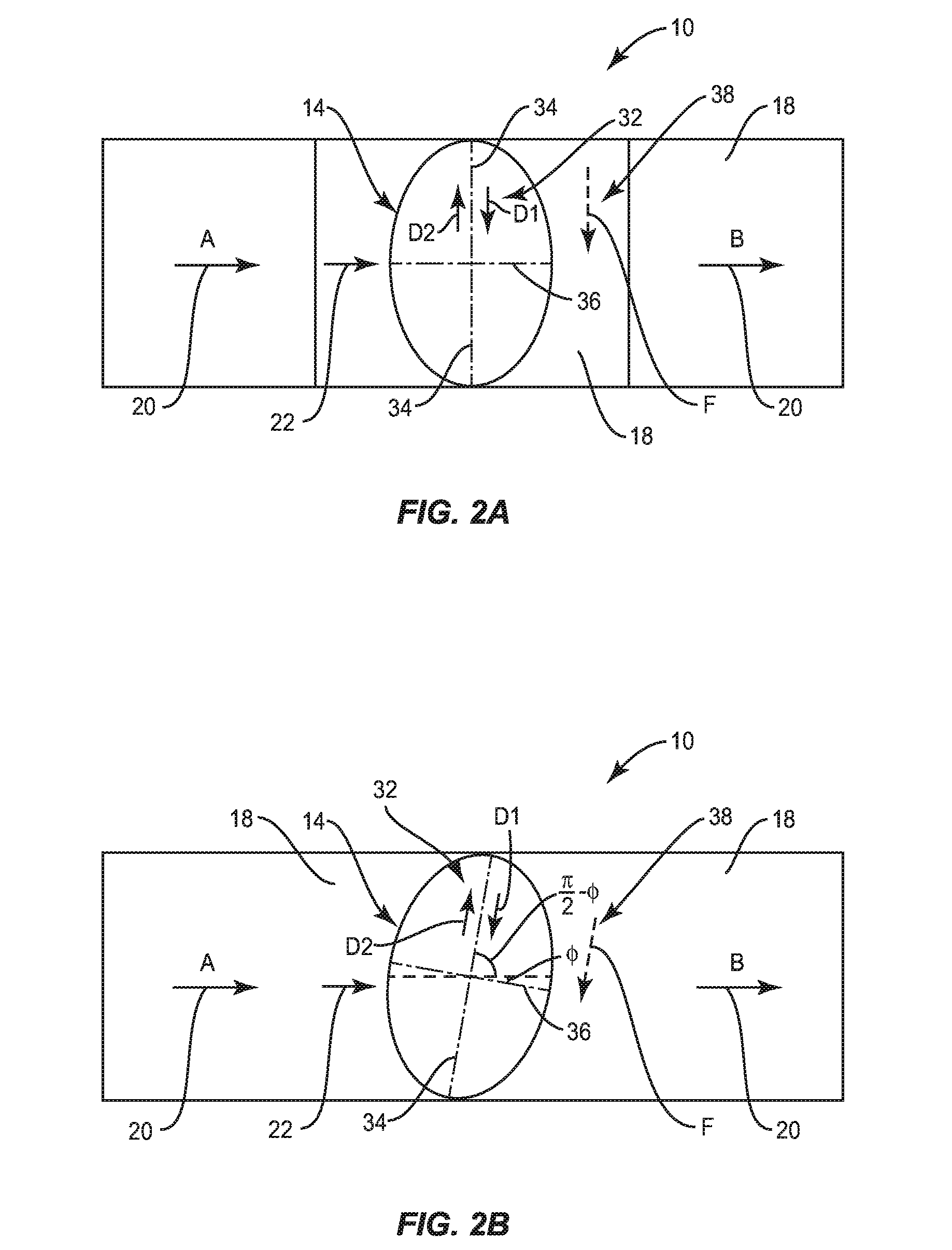
[0041]Aspects described herein are related to spintronic logic gates employing a Giant Spin Hall Effect (GSHE) magnetic tunnel junction (MTJ) element(s) for performing logical operations. Related systems and methods are also disclosed. More specifically, this disclosure describes aspects of spintronic logic gates that include one or more GSHE MTJ elements configured to perform logical operations. Methods of performing logical operations using one or more GSHE MTJ elements are also disclosed. Additionally, related aspects and methods of fabricating GSHE MTJ elements are disclosed. Since logical operations are performed using GSHE MTJ elements, the spin...


PUM


Abstract

Aspects described herein are related to pipeline circuits employing a Giant Spin Hall Effect (GSHE) magnetic tunnel junction (MTJ) element(s) for performing logical operations. In one aspect, a pipeline circuit is disclosed. The pipeline circuit includes a first pipeline stage and a second pipeline stage. The first pipeline stage is configured to store a first bit set and to generate a first charge current representing the first bit set. The second pipeline stage includes a first GSHE MTJ element. The first GSHE MTJ element is configured to set a first bit state for the first logical operation, and has a first threshold current level. The first GSHE MTJ element is configured to generate a first GSHE spin current in response to the first charge current. In this manner, the first GSHE MTJ element is also configured to perform the first logical operation on the first bit set.

Description

PRIORITY CLAIMS[0001]The present application claims priority to U.S. Provisional Patent Application Ser. No. 61 / 909,576 filed on Nov. 27, 2013 and entitled “SPINTRONIC LOGIC GATES FOR PERFORMING LOGIC OPERATIONS, AND RELATED SYSTEMS AND METHODS,” which is incorporated herein by reference in its entirety.[0002]The present application also claims priority to U.S. Provisional Patent Application Ser. No. 61 / 936,396 filed on Feb. 6, 2014 and entitled “SPINTRONIC LOGIC GATES FOR PERFORMING LOGIC OPERATIONS, AND RELATED SYSTEMS AND METHODS,” which is incorporated herein by reference in its entirety.[0003]The present application is a continuation of and claims priority to U.S. patent application Ser. No. 14 / 330,494, filed Jul. 14, 2014 and entitled “SPINTRONIC LOGIC GATES EMPLOYING A GIANT SPIN HALL EFFECT (GSHE) MAGNETIC TUNNEL JUNCTION (MTJ) ELEMENT(S) FOR PERFORMING LOGIC OPERATIONS, AND RELATED SYSTEMS AND METHODS,” which is incorporated herein by reference in its entirety.BACKGROUND[00...

Claims


Application Information

Patent Timeline
IPC IPC(8): H03K3/45H03K19/20H03K3/012H03K3/037
CPCH03K3/45H03K3/012H03K19/20H03K3/037H03K19/18G11C11/18G11C11/1675G11C11/161H10N50/10
Inventor WU, WENQINGMADALA, RAGHU SAGARYUEN, KENDRICK HOY LEONGARABI, KARIMGILMORE, ROBERT PHILIP
Owner QUALCOMM INC
Why Eureka
Try Eureka