

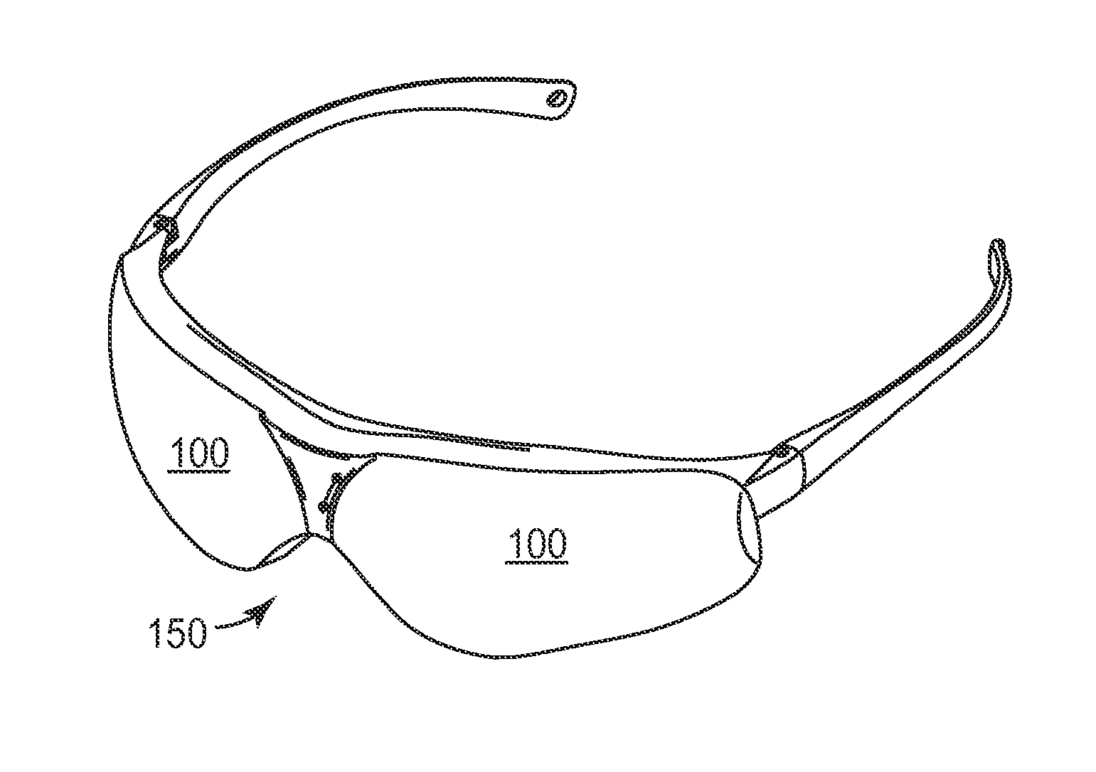
Blue edge filter optical lens
a filter optical and blue edge technology, applied in the field of blue edge filter optical lenses, can solve the problems of eye damage and lens with an unacceptable yellow appearan
- Summary
- Abstract
- Description
- Claims
- Application Information
AI Technical Summary
Benefits of technology
Problems solved by technology
Method used
Image

Examples
example 1
Violet Light Reflector
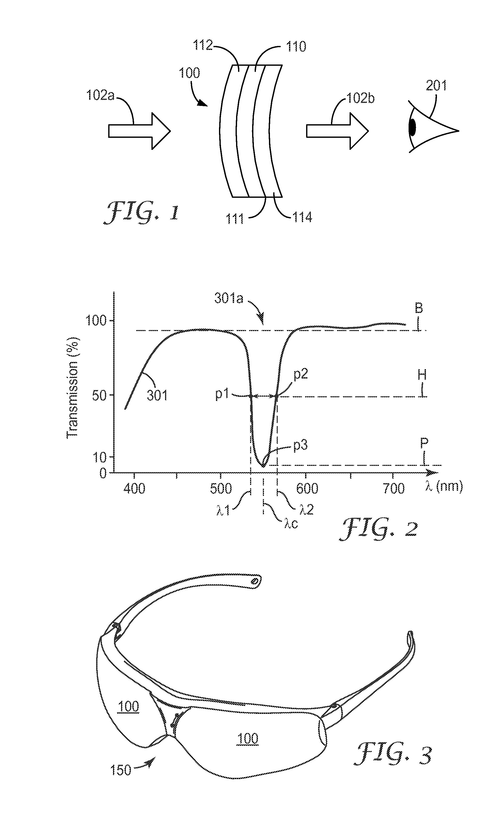
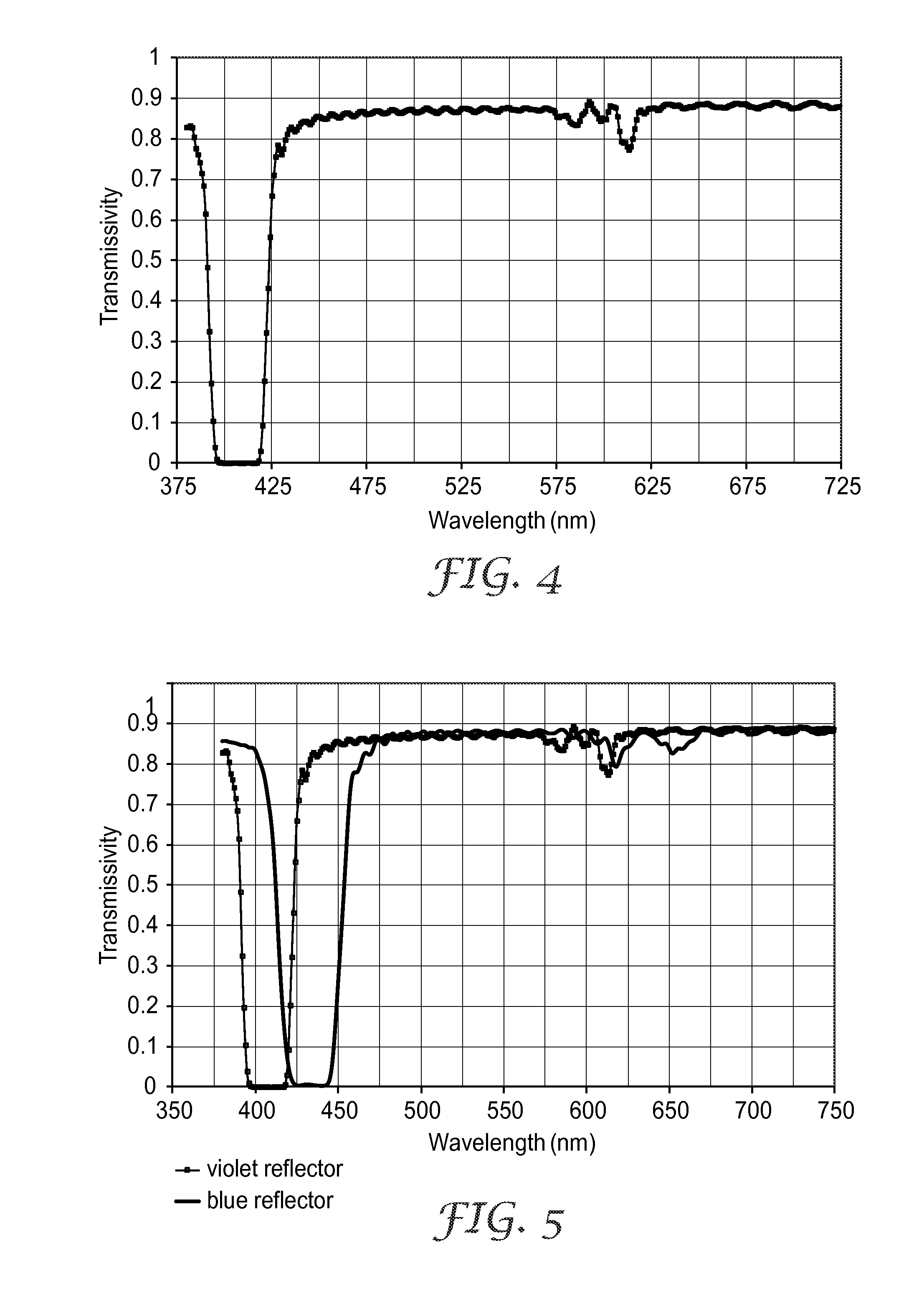
[0070]A film with 275 alternating layers of PET and coPMMA was coextruded and oriented with an f-ratio of approximately 0.5 and narrow layer thickness range to give a narrow but highly reflective 3rd order harmonic band in the violet region of the spectrum. A transmission spectrum of the film is plotted in FIG. 4. The FWHM of this band is about 31 nm. The transition from 5% T to 70% T for the long wavelength band edge (LWBE) is 6 nm wide. A weak 2nd order reflection band is visible near 600 nm due to small deviations from the condition of f-ratio=0.50 for some of the layer pairs in the stack. The average transmission from 398 nm to 418 nm is 0.1 percent (average transmissivity=0.001 being a 0.1% floor) and the average transmission from 400 to 420 nm is 0.6%. The sharp band edge of this filter enables the blocking of greater than 99% of violet light without adding any noticeable yellow coloration to the film.
[0071]Although the film does block light that is visib...
example 2
Violet and Blue (400 to 440 nm) Light Reflector
[0073]To provide for more protection from actinic radiation, the reflection band of Example 1 can be extended to block longer wavelengths of light beyond the violet portion of the spectrum. Extension of the blocking region to 430, 435 or 440 nm will increase the protection of the eye from macular degeneration. The spectrum can be extended by increasing the gradient of the layer thickness profile in the stack, or additional layers can be added to the stack, or a second independent stack can be added either by coextrusion or by laminating a separately formed stack to the first. Coextrusion of two different multilayer polymeric reflector stacks can be accomplished using the apparatus described in U.S. Patent Publication 2011 / 0272849 entitled “Feedblock for Manufacturing Multilayer Polymeric Films”, filed May 7, 2010. The spectral plots in FIG. 5 show the spectra of Example 1 (violet reflector) and a spectrum of a second film (blue reflecto...
example 3
Narrowband Yellow Light Reflector
[0079]A narrow band reflector of yellow light has been found to be useful in eyewear for enhancing the color of objects and images. A multilayer stack of 275 layers was formed with the same method described above and in Example 1 to give a 3rd order reflectance band centered near 580 nm with a FWHM of about 35 nm (564 nm to 599 nm) shown in FIG. 6. The sharp band edges permit a band of very good blockage with less than 1% average transmission from 568 to 592 nm which yields a 1% floor of 24 nm in width, compared to the FWHM value of 35 nm. The 50% transmission values for the short and long wave band edges are within 4 nm and 7 nm of the respective edges of the 1% floor. Due to its narrow value of both FWHM and the full width at 90% Max (FW90M) of 49 nm, it reflects or blocks very little green or red light and provides for enhanced color viewing when used by itself in eyewear. 90% max in this case would be near a measured transmission in air of about ...
PUM
 Abstract
Description
Claims
Application Information