Eureka AIR delivers breakthrough ideas for toughest innovation challenges, trusted by R&D personnel around the world.

Apparatus of photolithography process to liquid display panel and method thereof

Active Publication Date: 2015-05-28
TCL CHINA STAR OPTOELECTRONICS TECH CO LTD
View PDF4 Cites 3 Cited by
  • Summary
  • Abstract
  • Description
  • Claims
  • Application Information

AI Technical Summary

Benefits of technology

The present invention provides an apparatus and method for a photolithography process to a liquid display panel. The apparatus includes a platform, ultraviolet light source supply device, light distributing plate, controller, and power supplying device. Using ultraviolet light generated by ultraviolet light light-emitting diode lamps, the monomer mixed with liquid crystal molecules can react under the irradiation of ultraviolet light and the damage of ultraviolet light to the liquid crystal molecules can be prevented. This leads to improved production efficiency and quality of liquid display panels. The ultraviolet light light-emitting diode lamps can provide a steady and precise ultraviolet light without the need for preheating and has a longer life time compared to traditional ultraviolet light sources. This advancement promotes the useful time of the apparatus for a photolithography process on a liquid display panel.

Problems solved by technology

The liquid crystal molecules are therefore damaged and lose the properties of the liquid crystal molecules.
The consequences of the damaging the liquid crystal molecules by the ultraviolet light irradiation are very severe.
The display quality of the liquid display panel can be terrible.
Even the liquid display panel may be abandoned to result in enormous waste.
It is seriously disadvantageous to the industrialization of the liquid display panel.

Method used


Image

  • Apparatus of photolithography process to liquid display panel and method thereof
  • Apparatus of photolithography process to liquid display panel and method thereof
  • Apparatus of photolithography process to liquid display panel and method thereof

Examples


Embodiment Construction

[0034]The following descriptions for the respective embodiments are specific embodiments capable of being implemented for illustrations of the present invention with referring to appended figures.

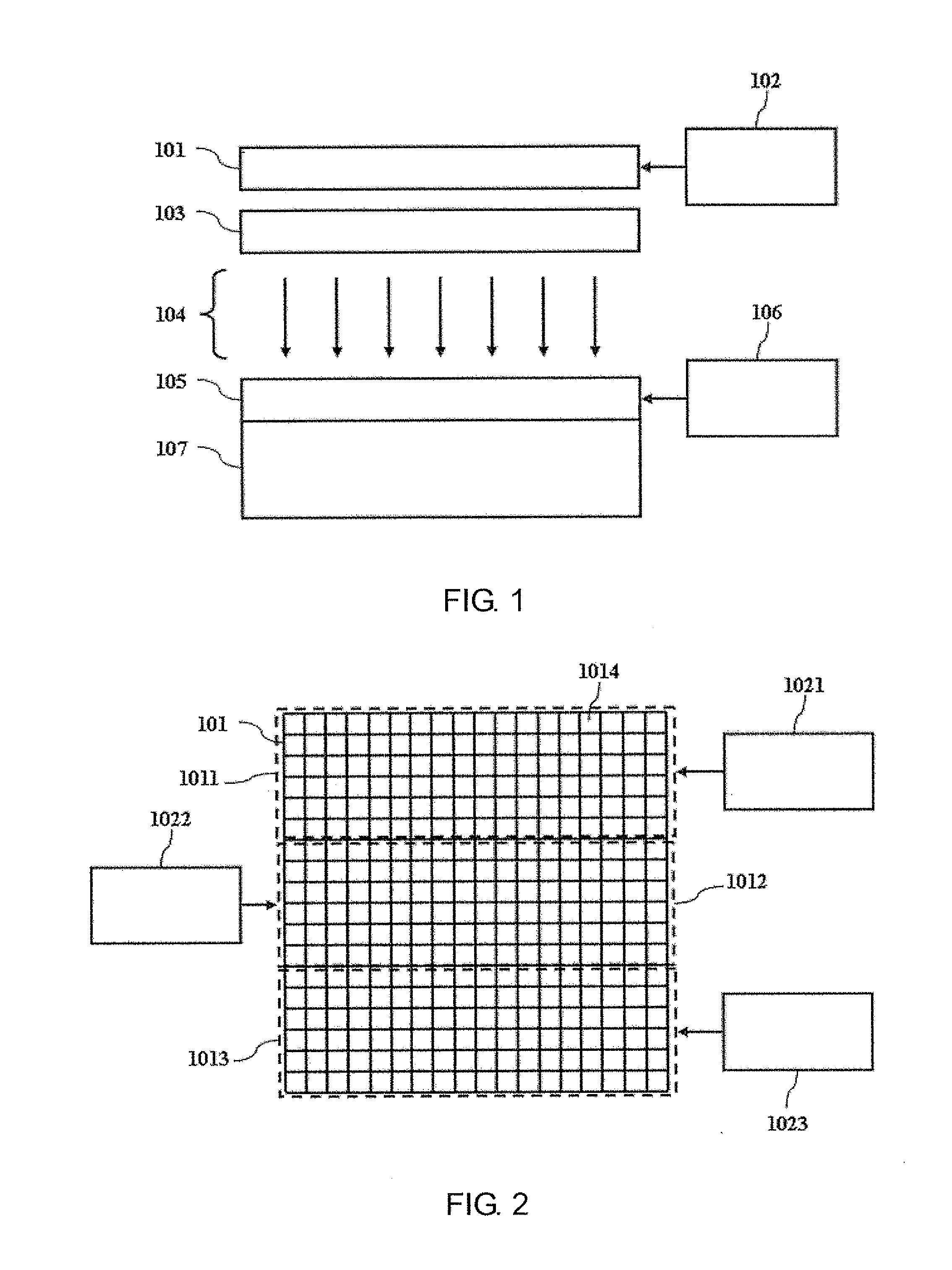
[0035]Please refer to FIG. 1, which depicts a diagram of an apparatus of photolithography process to a liquid display panel in-service condition according to the present invention. The apparatus of photolithography process to a liquid display panel according to the present invention comprises a platform 107, an ultraviolet light source supply device 101, a light distributing plate (Fly Eye) 103 and a power supplying device 106. The power supplying device 106 is electrically connected to the liquid display panel 105. The platform 107 is employed for loading a liquid display panel 105. The side of the ultraviolet light source supply device 101 generating the ultraviolet light faces the side of the platform 107 loading the liquid display panel 105. The light distributing plate 103 is positione...


PUM

PropertyMeasurementUnit
Angleaaaaaaaaaa
Wavelengthaaaaaaaaaa

Abstract

The present invention discloses an apparatus of photolithography process to a liquid display panel, comprising: a platform, employed for loading the liquid display panel; a power supplying device, employed for supplying power to the liquid display panel; an ultraviolet light source supply device, employed for providing the ultraviolet light; a light distributing plate, employed for homogenizing the ultraviolet light. The present invention also discloses a method of photolithography process to a liquid display panel. The monomer can plenty reacts without damaging liquid crystal molecules according to the present invention.

Description

BACKGROUND OF THE INVENTION[0001]1. Field of the Invention[0002]The present invention generally relates to a display apparatus field, and more particularly to an apparatus of photolithography process to a liquid display panel and a method thereof.[0003]2. Description of Prior Art[0004]In a traditional manufacture process of a liquid display panel, the liquid crystal molecules on PI (Polymer) surface with a consistent predetermined tilt angle is described below:[0005]Monomer is mixed with liquid crystal molecules and then the liquid display panel is electrified to cause the liquid crystal molecules with a predetermined tilt angle. Ultraviolet light is employed to irradiate the monomer. The monomer is solidified on the PI surface. Accordingly, the liquid crystal molecules on the PI surface are maintained with a certain angle.[0006]In the foregoing technical solution, the liquid crystal molecules and the monomer are mixed together. In the process of utilizing the ultraviolet light to i...

Claims


Application Information

Patent Timeline
IPC IPC(8): G03F7/20
CPCG03F7/70058G02F1/1303G02F1/133711G02F1/133788G02F2202/023G02F2203/03G03F7/70791
Inventor CHEN, HSIAO-HSIEN
Owner TCL CHINA STAR OPTOELECTRONICS TECH CO LTD
Why Eureka
Eureka Blog
Learn More