

Systems and method for protection of optical system of laser-based apparatus
a technology of laser-based apparatus and optical system, which is applied in the field of dental laser hand pieces, can solve the problems of blown away debris attached to the components achieve the effect of avoiding or reducing contamination of the optical subsystem
- Summary
- Abstract
- Description
- Claims
- Application Information
AI Technical Summary
Benefits of technology
Problems solved by technology
Method used
Image

Examples
Embodiment Construction
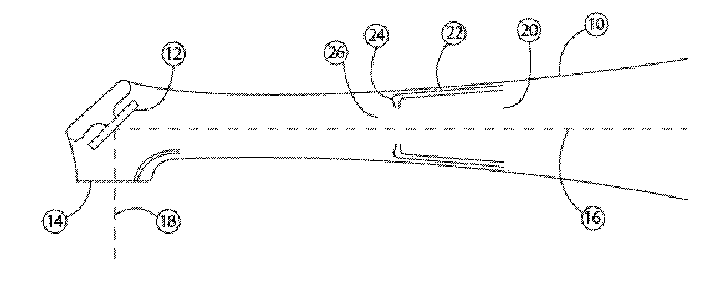
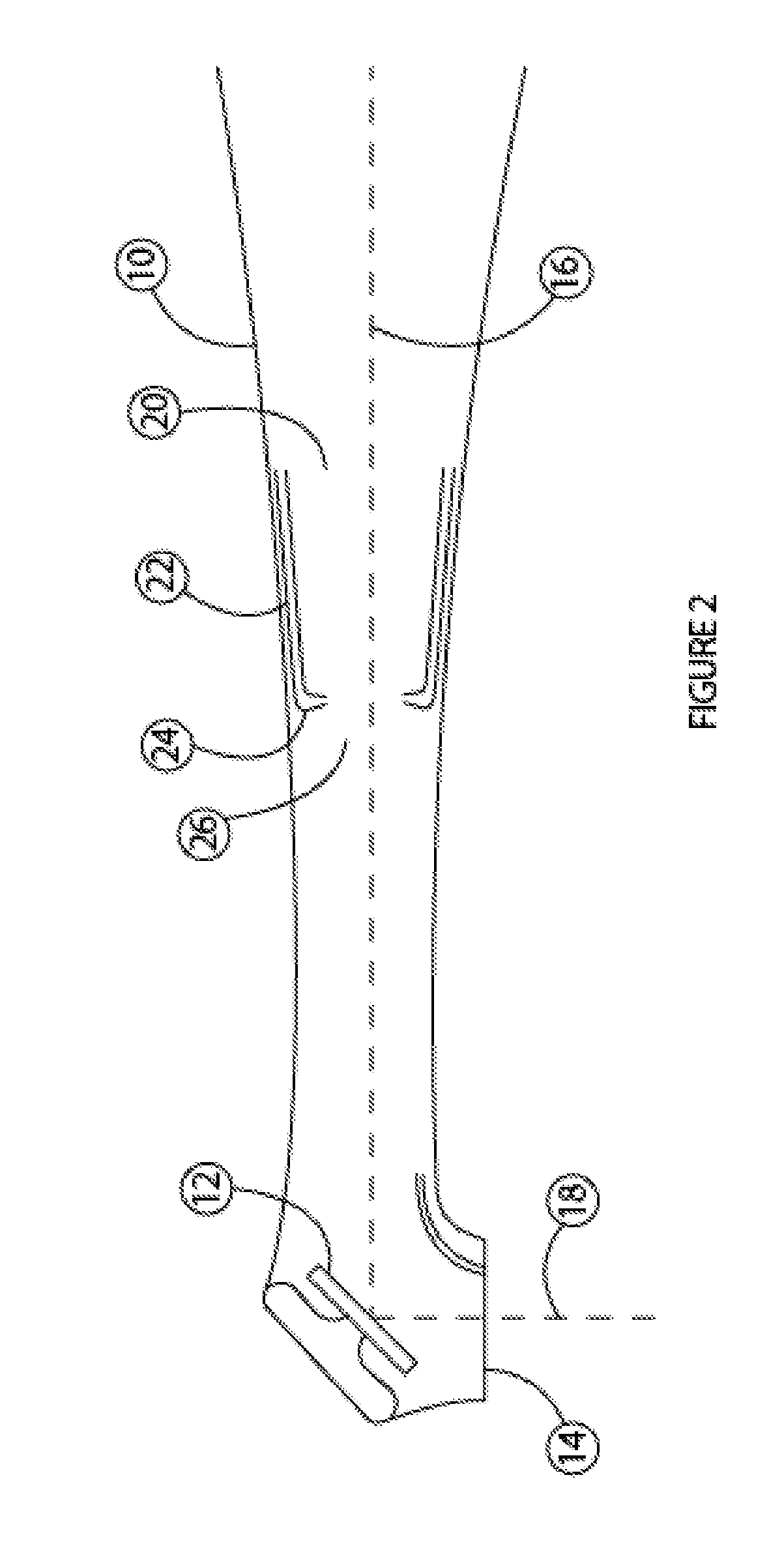
[0018]With reference to FIG. 2, a fluid supply subsystem 20 includes one or more conduits, such as tubes 22, and one or more nozzles 24. For example, the fluid supply subsystem 20 can provide a positive pressure within the hand piece 10, creating a high pressure cavity 26 therein. Due to a high pressure in the cavity 26, fluid (e.g., air) may flow substantially continuously within the hand piece 10 and out of the orifice 14. The fluid flow can impart forces opposing any contaminants ejected into the hand piece 10 through the orifice 14, or otherwise directed toward the reflector (e.g., a turning mirror) 12. The fluid flow out of the orifice is generally a function of fluid pressure and size of the orifice. For an exemplary orifice that is about 2.5 mm in diameter, a fluid pressure in the cavity 26 in a range from about 10 psi up to about 100 psi can significantly minimize the amount of debris attaching and / or remaining attached to the reflector 12. For example, without the fluid pre...
PUM
 Abstract
Description
Claims
Application Information