Lighting device and projector

a projector and light source technology, applied in the field of projectors and light sources, can solve the problems of color balance changes, white balance deviation, color balance deviation, etc., and achieve the effect of excellent display quality

Active Publication Date: 2015-06-04
SEIKO EPSON CORP
View PDF1 Cites 58 Cited by
  • Summary
  • Abstract
  • Description
  • Claims
  • Application Information

AI Technical Summary

Benefits of technology

[0021]Since the projector according to the aspect includes the lighting device according to the aspect of the invention, it is possible to provide a projector of which a display quality is excellent.

Problems solved by technology

However, with this configuration, it is not possible to correct the deviation in white balance any time, which is caused by a deterioration with time during use, even though deviation in white balance can be corrected before shipping the product.
In addition, it is not possible to correct deviation in color balance of colored light other than white light.
As a result, there is a problem that a color balance changes compared to the color balance before the deterioration with time.

Method used


Image

  • Lighting device and projector
  • Lighting device and projector
  • Lighting device and projector

Examples


first embodiment

[0033]Hereinafter, a first embodiment of the invention will be described using FIGS. 1 to 5.

[0034]A projector according to the first embodiment is an example of a liquid crystal projector which includes a lighting device which is one embodiment of the invention, and three optical modulation units.

[0035]Hereinafter, description will be given in detail using drawings; however, in order to make each constituent element easy to view in the following figure, there is a case in which a scale of a dimension is differently denoted depending on a constituent element.

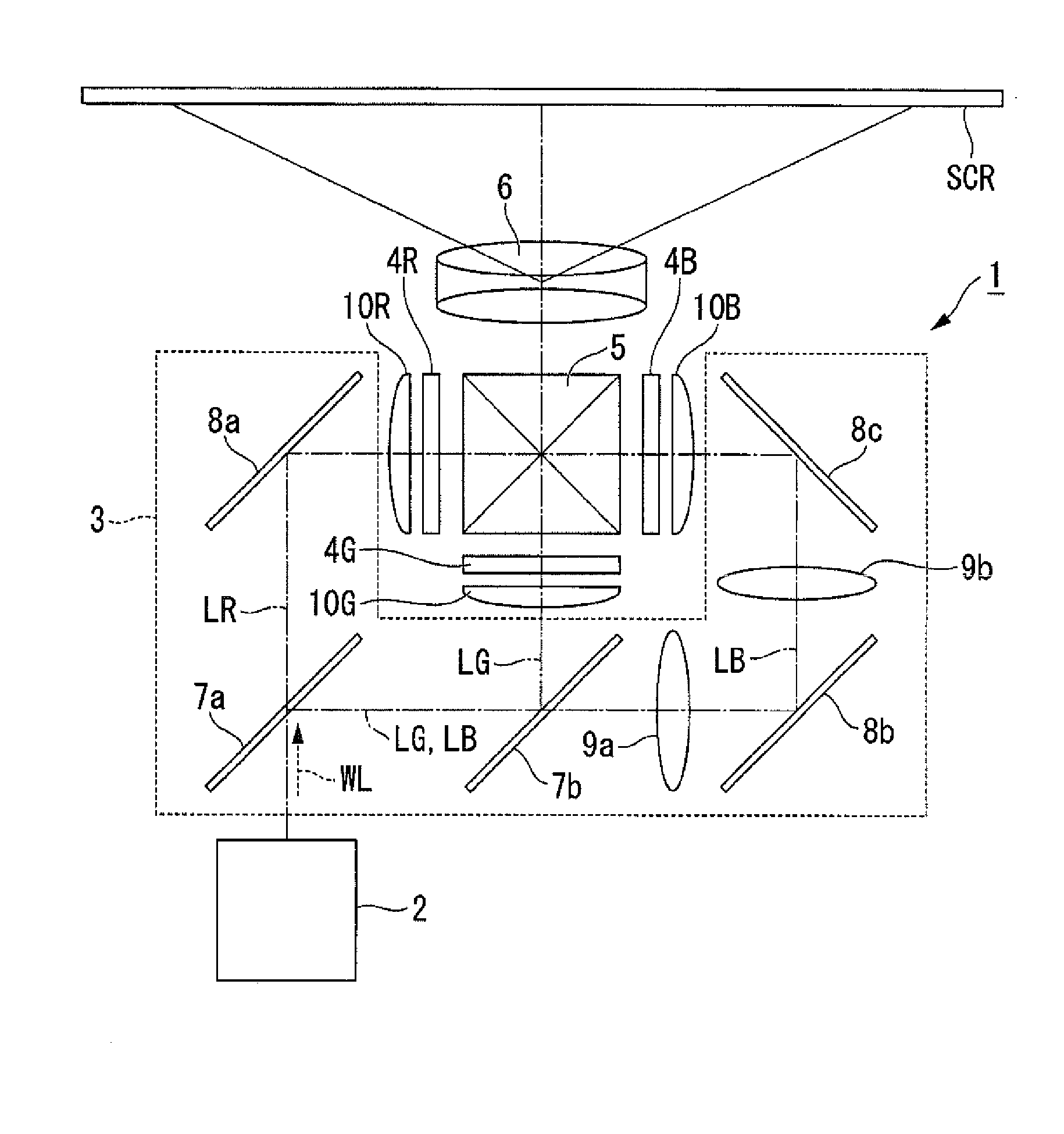
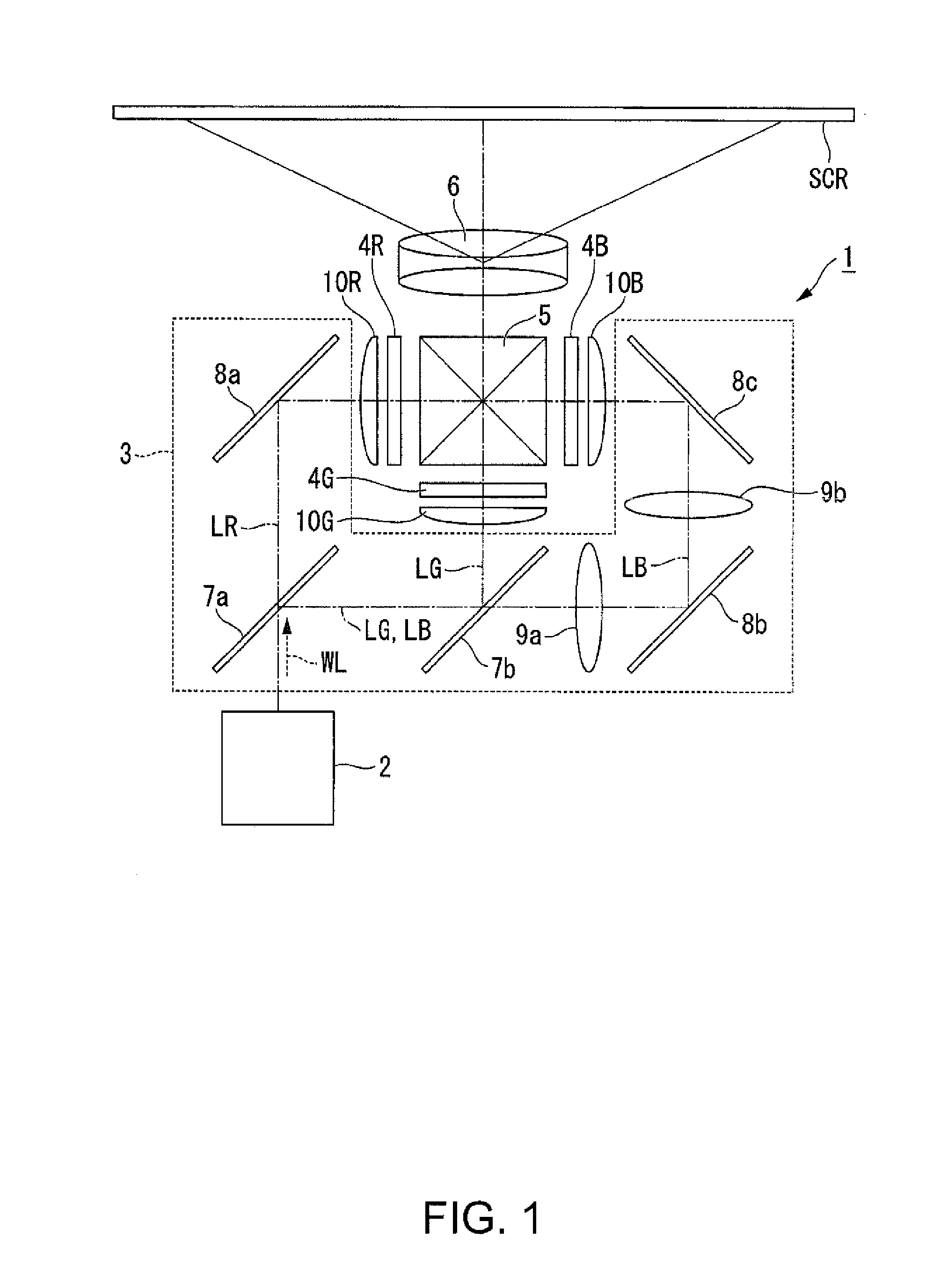
[0036]As illustrated in FIG. 1, a projector 1 according to the embodiment is a projection type image display device which displays a color image on a screen SCR. The projector 1 uses three optical modulation units corresponding to each color of light of red light LR, green light LG, and blue light LB. The projector 1 is equipped with a semiconductor laser that provides light with high luminance and a high output as a light source...

second embodiment

[0094]Hereinafter, a second embodiment of the invention will be described using FIG. 9.

[0095]A basic configuration of a lighting device according to the second embodiment is the same as that in the first embodiment, and a difference from the first embodiment is that a fluorescent substance layer which emits green light, and a fluorescent substance layer which emits red light are used instead of the fluorescent substance layer which emits yellow light.

[0096]FIG. 9 is a schematic configuration diagram of a lighting device according to the second embodiment.

[0097]In FIG. 9, common constituent elements in FIG. 2 which are used in the first embodiment are given the same reference numerals, and descriptions thereof will be omitted.

[0098]In the lighting device according to the first embodiment, the wavelength conversion unit is configured of the light emitting element 27. As illustrated in FIG. 9, in a lighting device 60 according to the embodiment, the wavelength conversion unit includes ...

third embodiment

[0117]Hereinafter, a third embodiment of the invention will be described using FIG. 10.

[0118]A basic configuration of a lighting device according to the third embodiment is the same as those in the first and second embodiments, a difference from those in the first and second embodiments being that a semiconductor laser for excitation light and a semiconductor laser for illumination light are separately included.

[0119]FIG. 10 is a schematic configuration diagram of the lighting device according to the third embodiment.

[0120]In FIG. 10, common constituent elements in FIG. 2 which are used in the first embodiment, and in FIG. 9 which are used in the second embodiment are given the same reference numerals, and descriptions thereof will be omitted.

[0121]As illustrated in FIG. 10, in a lighting device 80 according to the third embodiment, a configuration related to an optical path of the blue light BL configured of S-polarized light which is reflected on the first polarization separation ...


PUM


Abstract

In a lighting device, light in a first wavelength range which is output from a light emitting element passes through a first phase difference plate, and is separated into a first light flux and a second light flux by a polarization separation element. A wavelength conversion unit converts the first light flux to a third light flux. An optical element converts the second light flux into a fourth light flux. A first color combining element combines the third light flux with the fourth light flux. A first control unit changes a direction of an optical axis of the first phase difference plate according to an intensity of the third light flux and an intensity of the fourth light flux.

Description

BACKGROUND[0001]1. Technical Field[0002]The present invention relates to a lighting device and a projector.[0003]2. Related Art[0004]A light source device in which a fluorescent substance is excited by light which is output from a plurality of solid light sources, and fluorescence which is emitted from the excited fluorescent substance is used, and a projection type display device using the light source device are disclosed in the following JP-A-2012-137744. In the light source device, output light from the solid light source unit is separated by a polarization separation mirror, one of the separated light beams is guided to a fluorescent light emitting plate as excitation light, and the other of the separated light beams is combined with fluorescence, which is obtained from the fluorescent light emitting plate, to be illumination light. In addition, a rotatable phase difference plate is provided on an optical path between the solid light source unit and the polarization separation ...

Claims


Application Information

Patent Timeline
Patent Type & Authority Applications(United States)
IPC IPC(8): F21V9/14G03B21/20
CPCG03B21/2073F21V9/14G03B21/204H04N9/3158H04N9/3161H04N9/3182H04N9/3194
Inventor AKIYAMA, KOICHI
Owner SEIKO EPSON CORP
Why Eureka
Try Eureka