Optical device and virtual image display apparatus

Active Publication Date: 2015-06-04
SEIKO EPSON CORP
View PDF6 Cites 52 Cited by
  • Summary
  • Abstract
  • Description
  • Claims
  • Application Information

AI Technical Summary

Benefits of technology

[0007]Therefore, an advantage of some aspects of the invention is to provide an optical device and a virtual image display a

Problems solved by technology

However, a structure of U.S. Pat. No. 4,711,512 is complex, and particularly it is difficult to manu

Method used


Image

  • Optical device and virtual image display apparatus
  • Optical device and virtual image display apparatus
  • Optical device and virtual image display apparatus

Examples


first embodiment

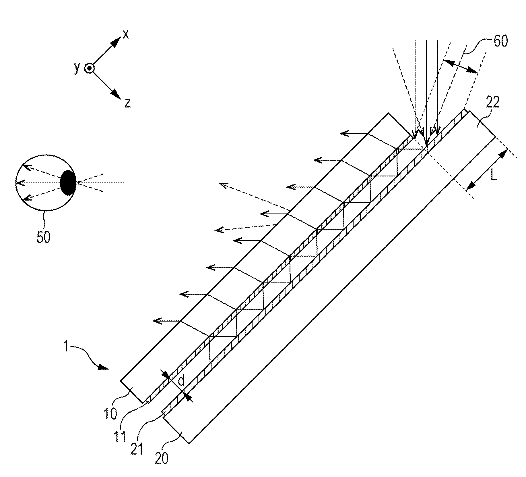
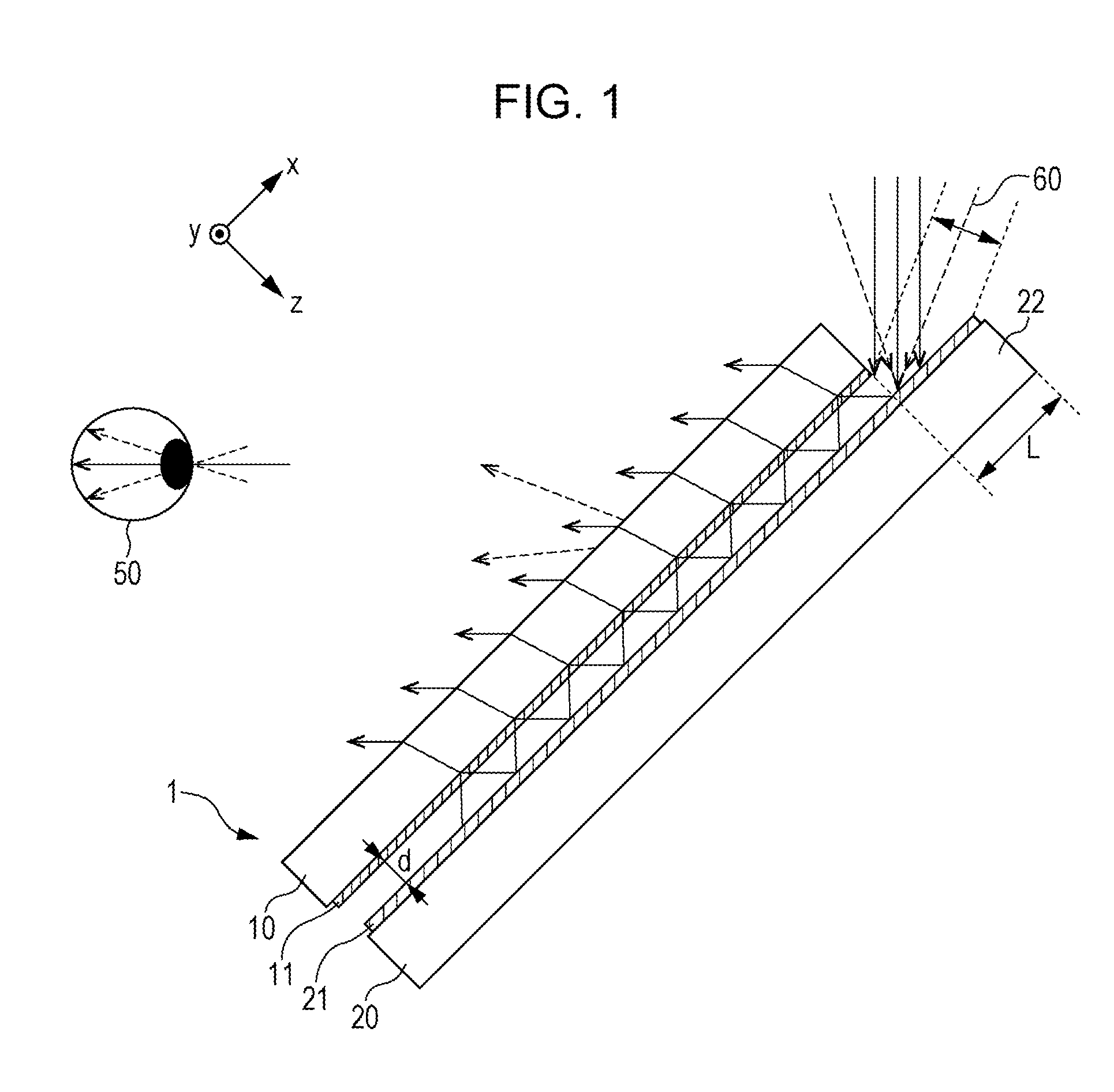
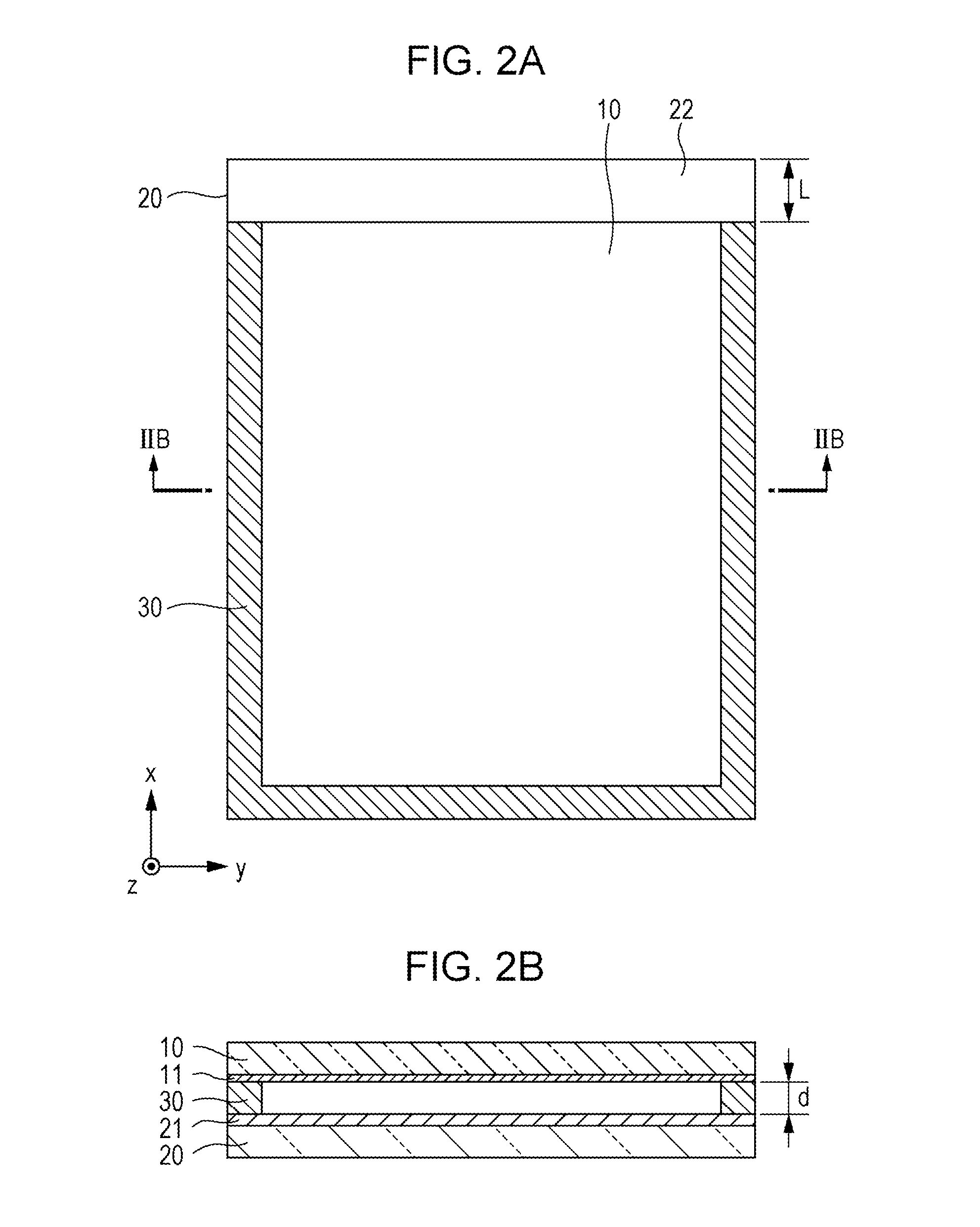
[0044]A first embodiment of the invention will be described with reference to FIGS. 1 to 5. As shown in FIG. 1, an optical device 1 of the embodiment includes: a first transparent substrate 20 that is made of glass or transparent resin; and a second transparent substrate 10 that is disposed in parallel with the first transparent substrate 20 and is made of glass or transparent resin. A partially transmissive reflective film 11 is formed on a surface of the second transparent substrate 10 facing the first transparent substrate 20. The partially transmissive reflective film 11 can be formed of a thin metallic film, a dielectric multilayer film, or the like. A high reflectance reflector 21, which is made of aluminum, silver, a dielectric multilayer film, or the like, is provided on a surface of the first transparent substrate 20 facing the second transparent substrate 10.

[0045]In the embodiment, the first transparent substrate 20 has a thickness of, for example, 1 to 10 mm, and has a s...

second embodiment

[0058]Subsequently, a second embodiment of the invention will be described with reference to FIG. 6. In the first embodiment, the partially transmissive reflective film 11 is provided on a side of a surface of the second transparent substrate 10 facing the high reflectance reflector 21. However, the second embodiment is an example in which the partially transmissive reflective film 11 is provided on the viewer side surface of the second transparent substrate 10.

[0059]As shown in FIG. 6, the partially transmissive reflective film 11 is provided on the viewer side surface of the second transparent substrate 10. Further, as the second transparent substrate 10, a substrate, which is thinner than the second transparent substrate 10 of the first embodiment, is used. Specifically, the second transparent substrate 10 has a thickness which is about 10% of the thickness of the air layer which guides light. For example, the second transparent substrate 10 is formed of a PET film of 10 μm.

[0060...

third embodiment

[0062]Subsequently, a third embodiment of the invention will be described with reference to FIGS. 7A and 7B. The first embodiment described the example of the optical device of the invention in which the pupil is enlarged. However, the third embodiment will describe an example of a virtual image display apparatus in which the pupil is enlarged through combination of an optical device of the related art and the optical device of the invention.

[0063]As shown in FIGS. 7A and 7B, in the embodiment, an optical device 70 using a diffraction grating such as a hologram or a half mirror array in the related art and the optical device 1 according to the embodiment of the invention are combined. As the optical device 70, for example, an optical device having a half mirror array 71 is used.

[0064]Incident light is diffused in the y direction by the optical device 70, and is made to be incident into the optical device 1 according to the embodiment of the invention, and the incident light is diffu...


PUM


Abstract

A partially transmissive reflective film is provided on a second transparent substrate, and a reflector is provided on a first transparent substrate. The partially transmissive reflective film and the reflector are held parallel to each other with a predetermined spacing therebetween. Thereby, light is incident from a protrusion portion on which the reflector of the first transparent substrate is formed, the light is reflected by the partially transmissive reflective film and the reflector, and the incident light is guided by an air layer between the partially transmissive reflective film and the reflector. A refractive index of the air layer is lower than that of the second transparent substrate. A part of the guided light is extracted from the partially transmissive reflective film, and is emitted from the second transparent substrate on a side opposite to a surface on which the partially transmissive reflective film is provided.

Description

BACKGROUND[0001]1. Technical Field[0002]The present invention relates to an optical device, which enlarges an exit pupil of a viewer system, and a virtual image display apparatus including the corresponding optical device.[0003]2. Related Art[0004]In the related art, virtual image displays for displaying a virtual image in an enlarged manner have been studied. However, since the exit pupil diameter of a single image device such as a liquid crystal panel is small, there has been a demand for a pupil enlargement technique having an excellent efficiency with a simple configuration. Further, there has also been a demand for an increase in the angle of view displayed.[0005]For example, in order to extract light from an optical device called a combiner, there has been proposed an apparatus using a diffraction grating (for example, U.S. Pat. No. 4,711,512). In U.S. Pat. No. 4,711,512, a diffraction grating, in which multiple inclined reflective faces are arranged, is used.[0006]However, a ...

Claims


Application Information

Patent Timeline
IPC IPC(8): G02B27/01G02B27/42G02B27/14
CPCG02B27/0101G02B2027/0123G02B27/4205G02B27/14G02B27/0081G02B5/30G02B27/106G02B27/144G02B27/145G02B27/017G02B2027/0174G02B2027/0125G02B2027/0178G02B2027/0118G02B6/0028G02B6/0056G02B6/0096G02B6/00
Inventor YONEKUBO, MASATOSHI
Owner SEIKO EPSON CORP
Why Eureka
Try Eureka