Local positioning and response system

a technology of local positioning and response system, applied in the field of positioning system, data processing system and communication system, can solve the problems of insufficient bandwidth, weak received signals, and inability to efficiently broadcast, so as to improve the efficiency of using potentially limited bandwidth

Active Publication Date: 2015-06-04
RYPPLZZ INC
View PDF4 Cites 5 Cited by
  • Summary
  • Abstract
  • Description
  • Claims
  • Application Information

AI Technical Summary

Benefits of technology

[0011]One or more embodiments described in the specification are related to a local positioning and response system. Embodiments of this system enable a local positioning and response system configured to transmit signals such as two or more shaped beams from at least one transmitter unit and devices that receive the shaped beams. The devices determine their local position in a defined area, such as a stadium, sports field, concert hall, amphitheater, theater, track, gymnasium, arena or any other location that may not enable access to satellite based positioning signals. The devices determine their individual responses based on their local position and on broadcast messages that may define aggregate responses for a group of devices in the area. A response may include, but is not limited to emitting a physical signal such as a light, sound, message of any type based on the local position determined by the device and the broadcast message. Thus embodiments of the system provide an efficient and effective system to generate responses in a potentially large number, or extremely large number of devices located in a local area. Embodiments of the system enable local positioning, in contrast to systems like GPS that provide absolute position relative to a worldwide reference frame. Some embodiments of the system may also incorporate GPS or similar absolute positioning systems as well, but do not require GPS.
[0019]Response units may calculate their local position using the intensity of the shaped beam signals that they receive. In some embodiments the intensity pattern of the shaped beam signals may be approximately Gaussian, which simplifies the calculation of the local position. In particular, relatively simple hardware may be used in the response units to derive local position from a combination of Gaussian signals. Some embodiments use the relative intensity multiple shaped beam signals rather than their absolute intensity. This approach offers the advantage of automatically compensating for many distortions of beams that emanate from the same beam transmitter. Other embodiments may employ any type of shaped beam pattern so long as the response units are aware of the type of beam employed.
[0022]Messages from the server to display graphical images may in some embodiments contain descriptions of one or more shapes, and potentially also of the shapes' motion over time. Such high-level graphics primitives in the messages allow messages to be efficiently broadcast to potentially large numbers of response units, with each response unit determining its appropriate output to form the aggregate images. Messages may also include error correcting (or error detecting) codes to eliminate the need for return acknowledgements or retransmissions, further improving efficient use of possibly limited bandwidth. Other message codes may be encrypted or otherwise protected to prevent third parties from hijacking the images or sounds displayed for example. In one or more embodiments, an event encryption code may be stored in the response units and utilized by the server and response units to encrypt and decrypt messages transmitted between the various components in the system.
[0024]Other applications in other embodiments may include feedback to sports players or coaches when a player moves into or out of a prescribed location, area, or trajectory. For example, a football receiver in practice may be practicing running a particular pattern. The player might wear a response unit that lights up or turns a different color if the player does not run the correct pattern. This feedback might alert coaches that the player made an error. Similar applications enable military troop movements to be sensed and otherwise observed and mapped and enables secure communication for devices that are within a predefined area.
[0028]Embodiments of the invention may also show winners at particular locations or show anyone who has entered a particular vote over the entire area, for example for users that voted for their favorite driver in a stock car race and for example after that driver has won the race. In addition, embodiments may provide more information for users that input or otherwise provide more information back to the server. Embodiments of the response units may include inputs that allow a user to register at an event and obtain more offers or increased capabilities, which may be of great value for corporate sponsors for example.

Problems solved by technology

While fairly successful in determining approximate location, these methods suffer from a number of limitations.
The received signals are so weak that even a tree canopy tends to attenuate the signals enough to preclude accurate positioning.
This technique is limited by the fortuitous placement of antenna towers, as well as by the sensitivity of the received signal strength to absorption along the signal path, reflections, and diffraction.
These effects render this technique of positioning inaccurate, limiting the accuracy in dynamic and unpredictable ways.
There are no known existing systems that provide accurate local positioning in a limited area with inexpensive devices.
In addition, many applications require that a potentially large number of devices in a limited area create a response that is observable in aggregate.
Technologies exist to provide communication between central systems and a network of devices; however these systems generally use point-to-point communication and require significant bandwidth as well as significant power and cost in the devices.
Further issues such as privacy and anonymous addressing of the devices make mobile phones and other handheld devices less desirable for this application.
The number of usable devices that may respond to system messages is growing dramatically, and current system architectures are not suited to handle this growth.
All these thousands of transceivers will occupy the same limited portion of the radio spectrum and thus the data rate available for communicating with any individual unit will become vanishingly small, in effect debilitating the wireless communicating capability of the devices.
Existing system architectures, which are based largely on point-to-point communication, cannot handle these requirements.
Moreover the systems that provide location-awareness, such as GPS, require expensive transmitters and receivers and are ill-suited for widespread application and low-cost, low-power devices.

Method used


Image

  • Local positioning and response system
  • Local positioning and response system
  • Local positioning and response system

Examples


Embodiment Construction

[0043]A local positioning and response system will now be described. In the following exemplary description numerous specific details are set forth in order to provide a more thorough understanding of embodiments of the invention. It will be apparent, however, to an artisan of ordinary skill that the present invention may be practiced without incorporating all aspects of the specific details described herein. In other instances, specific features, quantities, or measurements well known to those of ordinary skill in the art have not been described in detail so as not to obscure the invention. Readers should note that although examples of the invention are set forth herein, the claims, and the full scope of any equivalents, are what define the metes and bounds of the invention.

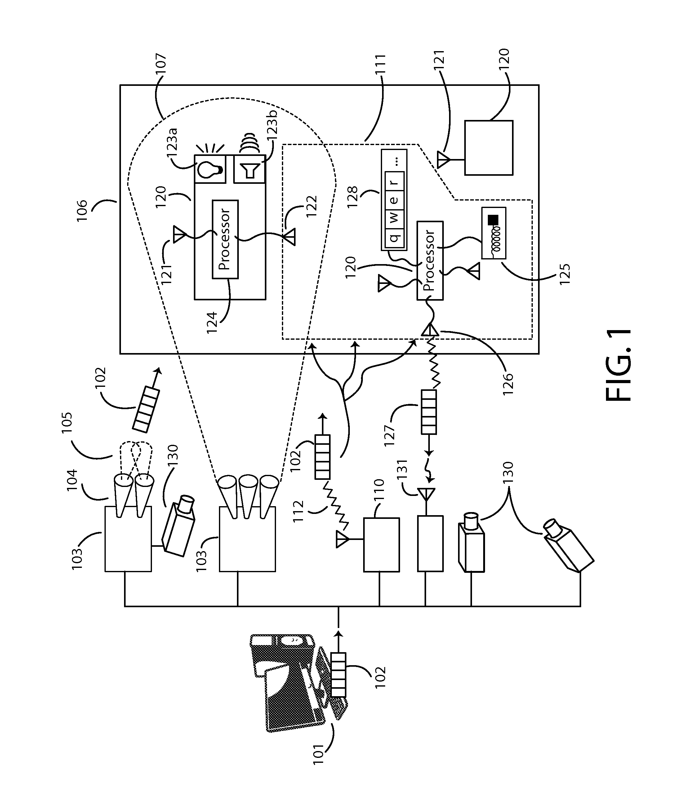
[0044]FIG. 1 illustrates an architectural view of at least one embodiment of the local positioning and response system, including exemplary components that may be utilized therewith. Such a system provides mecha...


PUM


Abstract

Enables a local positioning and response system that allows devices in a defined area to determine their local positions in the area, and to generate individual responses based on their positions, for example based on broadcast messages. Responses can include light, sound, shock, vibration, temperature or any other physical signal. Positioning may use overlapping shaped beam signals that permit each device to determine its local position. Response to broadcast messages with local position dependency enables efficient communication with potentially thousands or millions of response units over limited bandwidth channels. Efficient communication may also be supported by messages containing high-level graphical primitives, with devices determining their individual contributions to an aggregate image. The system may also provide correction for image distortions. Applications include stadium light or sound shows, virtual fences, feedback on performance that requires specific motions or positions, and contests for event spectators.

Description

[0001]This application claims the benefit of U.S. Provisional Patent Application Ser. No. 61 / 916,380, filed 16 Dec. 2013 and U.S. Provisional Patent Application Ser. No. 61 / 910,843, filed 2 Dec. 2013, the specifications of which are hereby incorporated herein by reference.BACKGROUND OF THE INVENTION[0002]1. Field of the Invention[0003]One or more embodiments of the invention are related to the field of positioning systems, data processing systems and communication systems. More particularly, but not by way of limitation, one or more embodiments of the invention enable a local positioning and response system configured to transmit signals such as two or more shaped beams from at least one transmitter unit and devices that receive the shaped beams. The devices determine their local position in a defined area, such as a stadium or other venue that may not enable access to satellite based positioning signals. The devices determine their individual responses based on their local position...

Claims


Application Information

Patent Timeline
Patent Type & Authority Applications(United States)
IPC IPC(8): H04W64/00H04W4/02
CPCH04W4/02H04W64/00G01S1/14G01S5/12G01S5/16G01S2201/01G01S1/7038G01S1/7034
Inventor SHCHEGLOV, KIRILLBERQUAM, PHILLIP
Owner RYPPLZZ INC
Why Eureka
Try Eureka