Electrode for polishing hollow tube, and electrolytic polishing method using same

a technology of electrolysis and hollow tubes, applied in the direction of electrolysis components, printed circuit manufacture, manufacturing tools, etc., can solve the problems of deterioration of polishing liquid, unfavorable electrolysis, and non-uniform texture of inner surface, etc., to achieve acceleration, short time, and high quality

Active Publication Date: 2015-06-11
MARUI MEKKI INDS
View PDF1 Cites 4 Cited by
  • Summary
  • Abstract
  • Description
  • Claims
  • Application Information

AI Technical Summary

Benefits of technology

[0024]According to the present invention, the distance between the hollow tube ad the electrode becomes uniform at any part of the hollow tube, and it is possible to perform the uniform polishing on all the inner surfaces of the hollow tube in a short time. Therefore, the internal texture of the hollow tube becomes uniform, and it is possible to realize the acceleration with high quality when the hollow tube is used as the accelerator for positrons and electrons. The present invention can be applied to the polishing for the hollow tube having uneven inner surfaces, and the application of the hollow tube is not limited to the accelerator. In addition, the present invention can be applied not only to the electrolytic polishing but also to the electrolytic plating, as a matter of course.

Problems solved by technology

The hollow tube 100, however, is subjected to an excessive pressure and heat at the formation, so that a texture of an inner surface becomes distorted non-uniformly.
If this surface status is left alone, the electric properties and the magnetic properties become uneven, too, with the result that it is impossible to impart a predetermined speed to the electrons and the positrons.
However, the outer surface of the hollow tube, which is not required to be polished, is polished concurrently, and it accelerates the unnecessary contamination, the aging, and the deterioration of the polishing liquid.
Moreover, there is a problem that a polishing amount differs notably depending on an immersion direction of a polishing object.
Such incident is involved in an action of stirring the polishing liquid by a produced gas, and the produced gas sticks to the inner surface of the tube due to the shape of hollow tube and damages the polished appearance, which results in many drawbacks.
In the above-mentioned method, the outer surface of the hollow tube not to be polished is polished at the same time that the inner surface is polished, as a result, the unnecessary dissolving loss of the hollow tube occurs and the polishing liquid is consumed unnecessarily and contaminated.
Moreover, the polishing unevenness occurs due to the intermittent polishing, and the operation is very dangerous because of handling the fluoric acid that is high volatile and produces toxic gas, and the sulfuric acid that is a high pyrogenic substance.
However, since it is configured that the nozzles provided to the liquid feed pipe are opened in the polishing liquid and the polishing liquid is discharged into the stored polishing liquid, the difference between the flow rates of the polishing liquid appears in the state of the polishing, and the unevenness of the polished appearance occurs on the inner surface of the niobium hollow tube, which is a problem, too.

Method used


Image

  • Electrode for polishing hollow tube, and electrolytic polishing method using same
  • Electrode for polishing hollow tube, and electrolytic polishing method using same
  • Electrode for polishing hollow tube, and electrolytic polishing method using same

Examples


Embodiment Construction

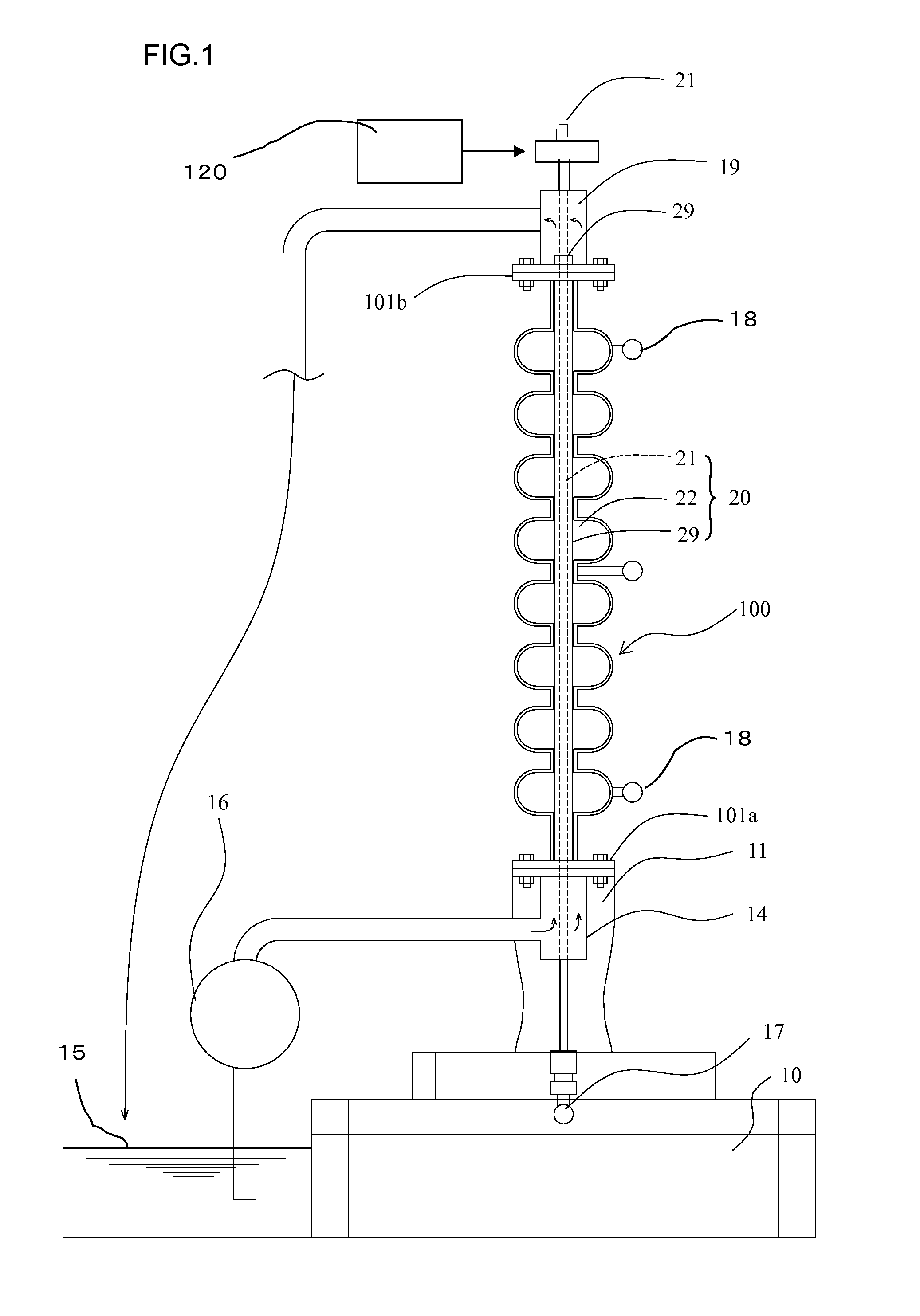
[0038]FIG. 1 is a view indicating a state that the electropolishing is performed on a hollow tube using an electrode in accordance with the present invention. FIG. 2 to FIG. 5 are basically schematic views indicating one section (corresponding to a bulge of the hollow tube) of the electrode that the invention employs. First, the section of the electrode is explained hereinafter.

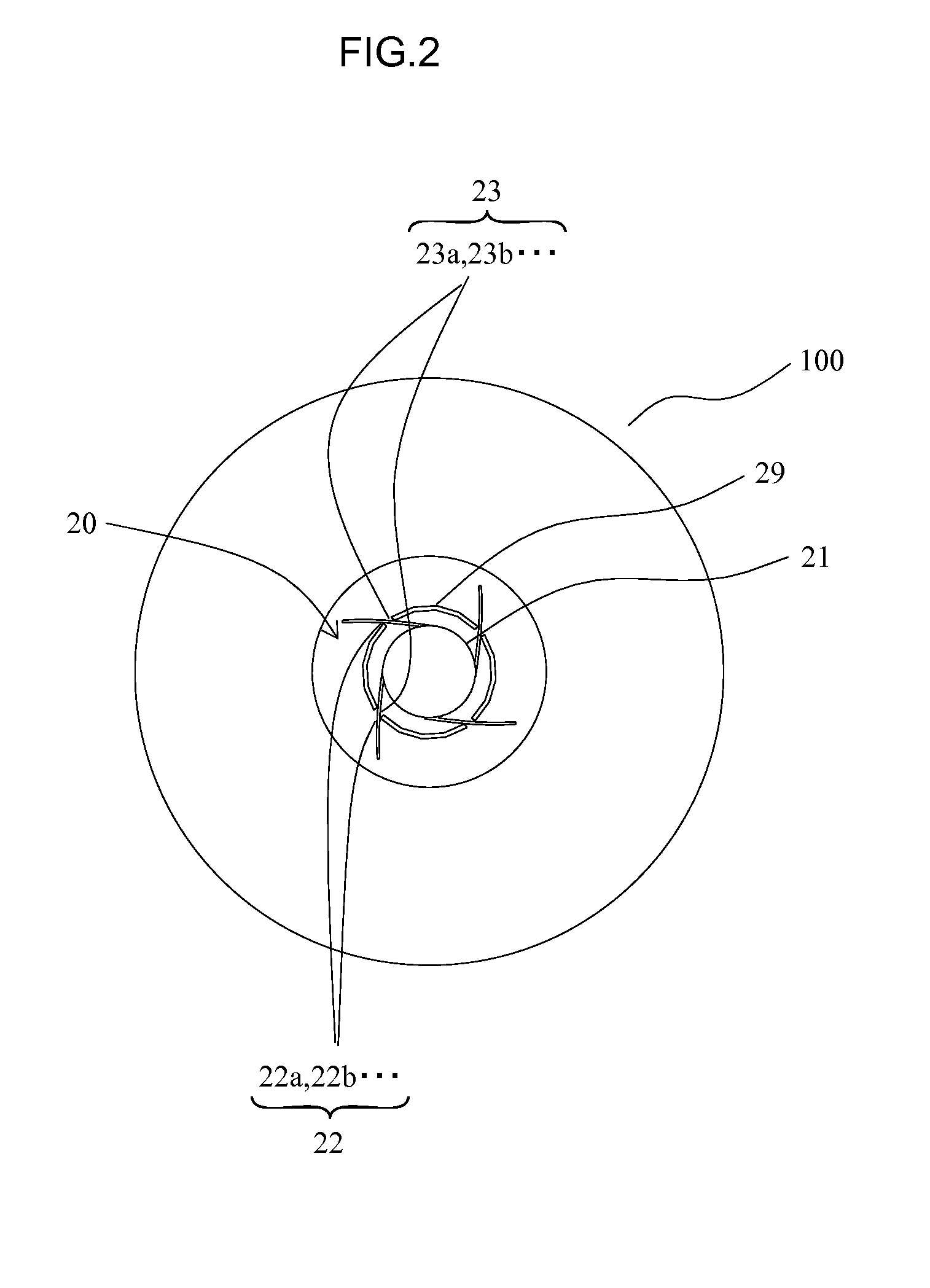
[0039]FIG. 2 is a plan view indicating the state before use of the electrode installed in the hollow tube, and FIG. 3 is a sectional view of the state. FIG. 4 is a plan view indicating the use state of the electrode installed in the hollow tube, and FIG. 5 is a sectional view of the state.

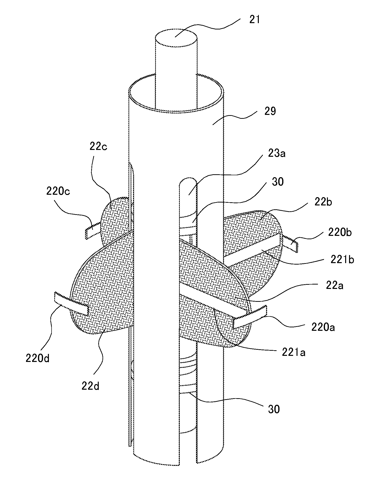
[0040]A wing electrode 22 is formed on an electrode shaft 21 by arranging at least one or plural wings 22a, 22b . . . in a circumferential direction of the electrode shaft 21 at equal intervals, the wing is made of a thin plate of which a base has a specific width in an axial direction, and an outer edge of the wing has a sh...


PUM

PropertyMeasurementUnit
distanceaaaaaaaaaa
thicknessaaaaaaaaaa
voltageaaaaaaaaaa

Abstract

A wing electrode is configured by disposing at least a wing in a circumferential direction at equal intervals, the wing having a specific width in an axial direction of the electrode shaft and a tip in a shape corresponding to an inner surface of the hollow tube. A housing tube is arranged concentrically to the electrode shaft and to house the wing electrode by winding the respective wings around the electrode shaft. A slit of the housing tube is arranged in the axial direction so as to correspond to each wing. A diameter adjustment unit is operable to expand and contract each wing in the radial direction by rotating the electrode shaft and the housing tube relatively after inserting each wing into the slit of the housing tube. As a matter of course, the electrolyte is filled in the hollow tube at any time before the electrolytic treatment.

Description

TECHNICAL FIELD[0001]The present invention relates to an electrode for electropolishing an inner surface of a hollow tube and an electropolishing method using the electrode.BACKGROUND ART[0002]A linear collider will be constructed as an apparatus for creating a state of Big Bang by the collision of positrons and electrons (International Linear Collider Project). The linear collider uses a hollow tube 100 made of niobium, which is provided with flanges 101a and 101b at both ends, and has a diameter changing periodically in an axial direction, as shown in FIG. 13. There are requirements to obtain a predetermined effect in this experiment, and one requirement is that the inner surface of the niobium hollow tube 100 is to be smooth.[0003]The hollow tube 100, however, is subjected to an excessive pressure and heat at the formation, so that a texture of an inner surface becomes distorted non-uniformly. If this surface status is left alone, the electric properties and the magnetic properti...

Claims


Application Information

Patent Timeline
Patent Type & Authority Applications(United States)
IPC IPC(8): C25F7/00C25F3/16
CPCC25F3/16C25F7/00C25F7/02
Inventor IDA, YOSHIAKI
Owner MARUI MEKKI INDS
Why Eureka
Try Eureka