Flow control valve for construction machinery

a technology for construction machinery and flow control valves, which is applied in mechanical equipment, servomotors, transportation and packaging, etc., can solve the problems of deterioration of fuel efficiency and manipulability, energy loss, energy loss, etc., and achieve the effect of preventing excessive pressure loss, improving fuel efficiency, and increasing boom-down operation speed

Active Publication Date: 2015-06-11
VOLVO CONSTR EQUIP AB
View PDF2 Cites 11 Cited by
  • Summary
  • Abstract
  • Description
  • Claims
  • Application Information

AI Technical Summary

Benefits of technology

[0041]Accordingly, the present invention has been made to solve the aforementioned problems occurring in the prior art, and it is an object of the present invention to provide a flow rate control valve for a construction machine in which the amount of a hydraulic fluid being returned to a hydraulic tank is reduced by separation and regeneration during the boom-down operation of a large-scale excavator so that a heat generation or an energy loss caused by an excessive pressure loss can be reduced, thereby increasing the fuel efficiency.

Problems solved by technology

For this reason, a pressure of the hydraulic pump rises during the boom-up operation, and an excessive pressure loss is caused by the returning of the high flow rate of hydraulic fluid during the boom-down operation, leading to an energy loss.
In particular, in case of a large scale construction machine, since a high flow rate of hydraulic fluid is returned from the large chambers of two boom cylinders, it causes an excessive pressure loss while passing through each passage, each spool, each poppet and the like of the control valve, resulting in an energy loss.
Further, a problem associated with the heat generation caused by the excessive pressure loss and a decrease in the boom-down operation speed lead to deterioration of fuel efficiency and manipulability.

Method used


Image

  • Flow control valve for construction machinery
  • Flow control valve for construction machinery
  • Flow control valve for construction machinery

Examples


Embodiment Construction

[0085]Now, a flow rate control valve for a construction machine in accordance with a preferred embodiment of the present invention will be described in detail with reference to the accompanying drawings. The matters defined in the description, such as the detailed construction and elements, are nothing but specific details provided to assist those of ordinary skill in the art in a comprehensive understanding of the invention, and the present invention is not limited to the embodiments disclosed hereinafter.

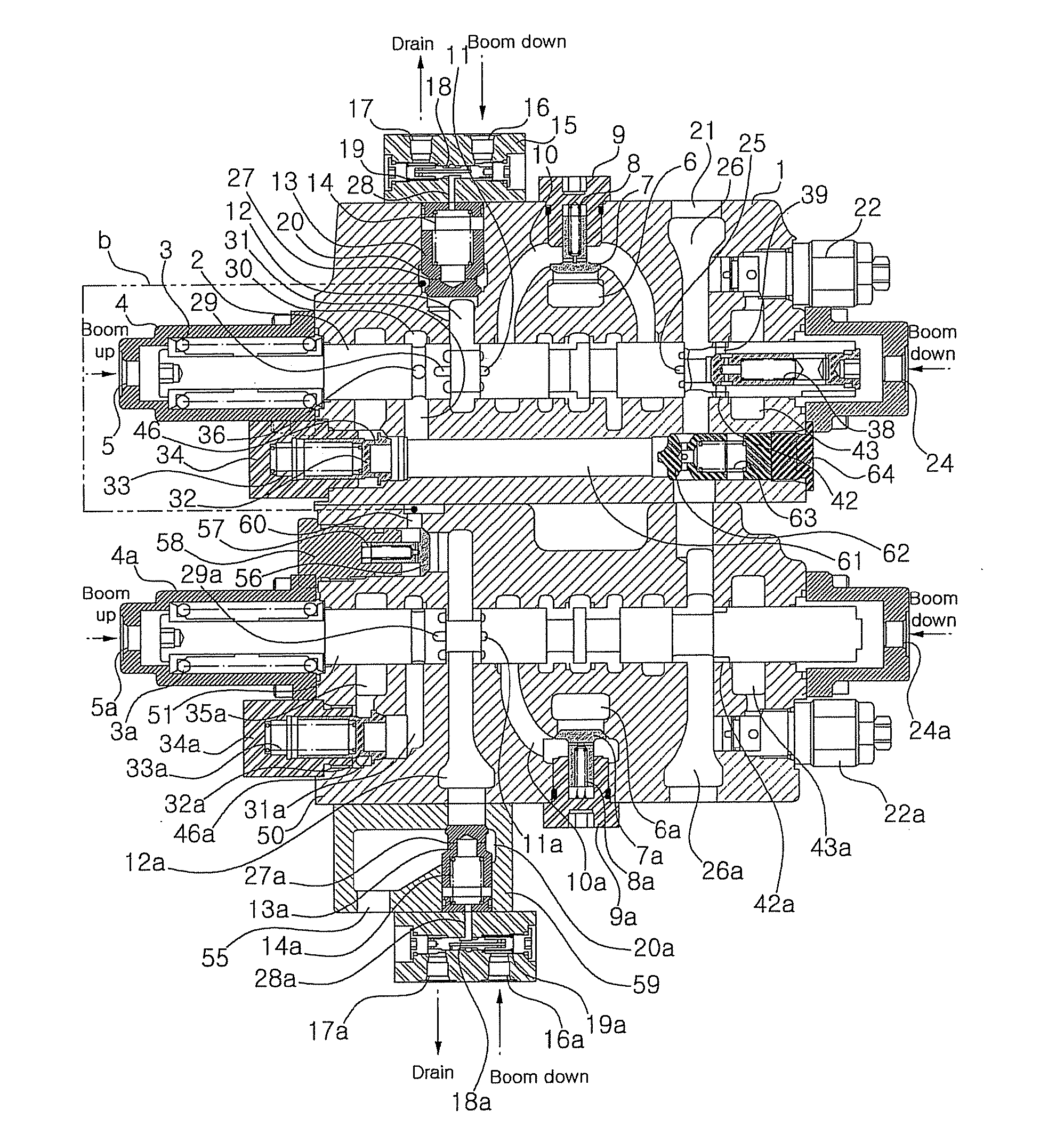
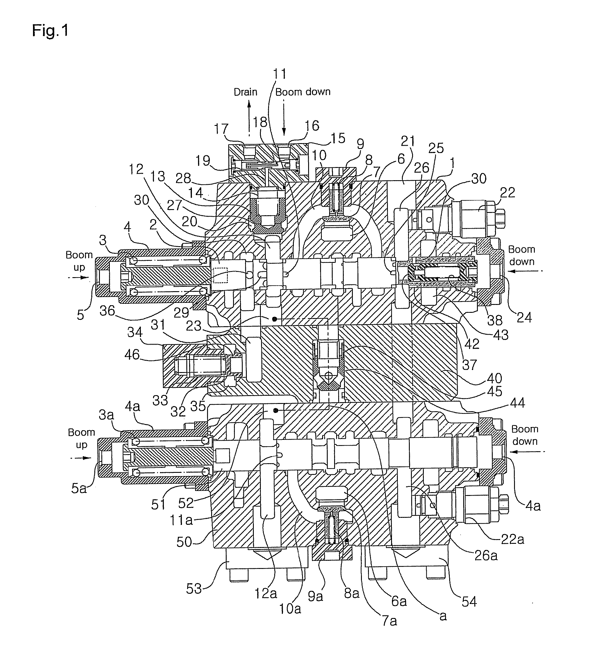
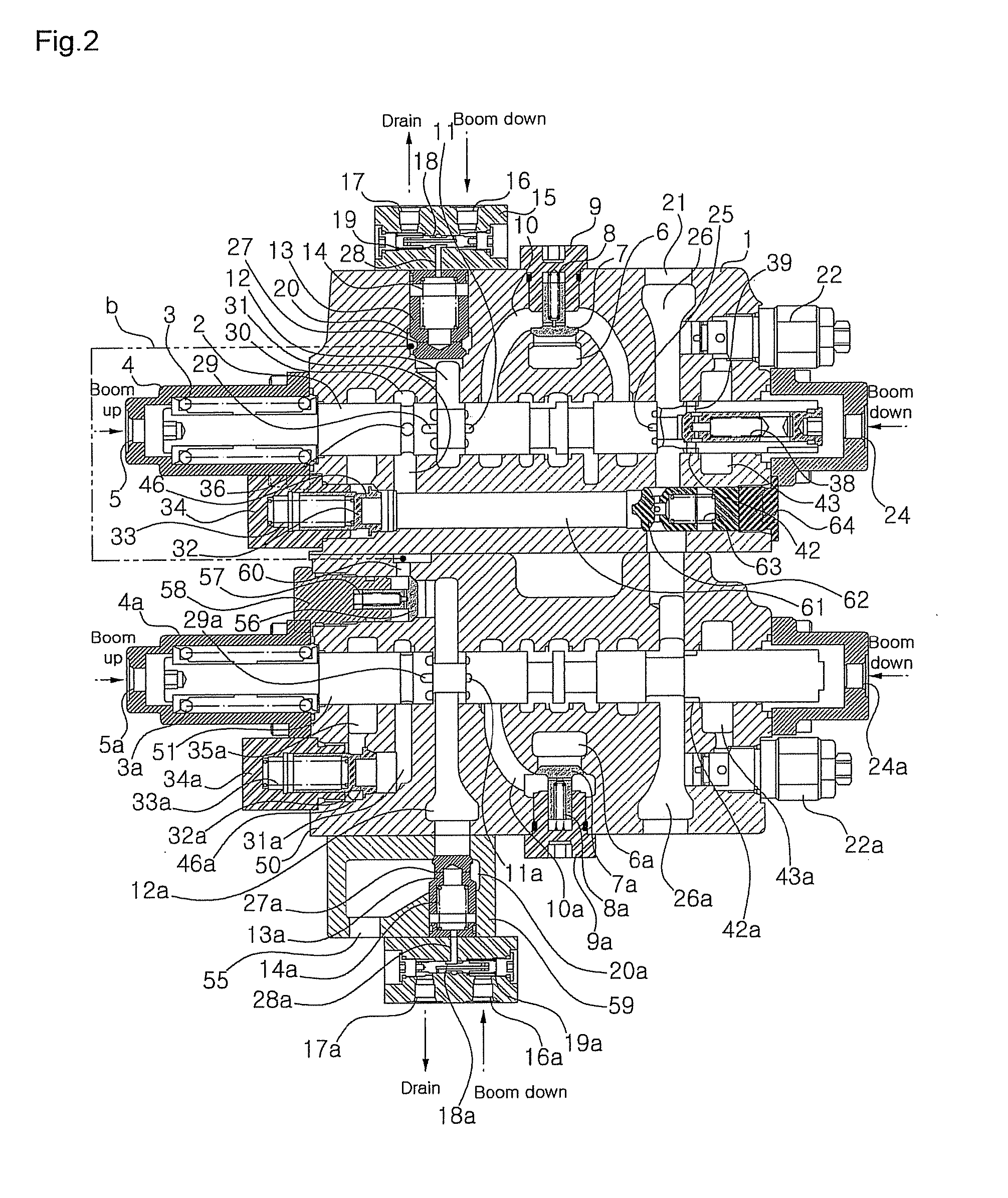
[0086]FIG. 2 is a cross-section view showing a flow rate control valve for a construction machine in accordance with a preferred embodiment of the present invention.

[0087]Referring to FIG. 2, the flow rate control valve for a construction machine in accordance with a preferred embodiment of the present invention, which is configured to control the supply of a hydraulic fluid to a hydraulic actuator from first and second hydraulic pumps, includes:

[0088]a first boom valve block 1 co...


PUM


Abstract

Disclosed is a flow control valve for construction machinery, the flow control valve being adapted to reduce pressure loss due to flow on return to a hydraulic tank during the boom-down operation of a large-scale excavator. The flow control valve for construction machinery according to the present invention comprises: first and second boom spools which are respectively coupled to first and second boom valve blocks, and which regulate working fluid that is respectively supplied from first and second hydraulic pumps to a boom cylinder during direction reversal; a boom-up flow-adjusting means which, in direction reversal of the first and second boom spools for boom-up drive, supplies working fluid from the first and second hydraulic pumps into a large chamber of the boom cylinder via the first and second boom spools respectively, and causes part of the flow of working fluid from the second hydraulic pump to pass via the second boom spool so as to be combined with working fluid being supplied from the first hydraulic pump to the large chamber of the boom cylinder due to direction reversal of the first boom spool; and a boom-down flow-adjusting means which, in direction reversal of the first and second boom spools for boom-down drive, causes part of the flow of working fluid coming back from the large chamber of the boom cylinder to return to the hydraulic tank via the first and second boom spools respectively, and causes part of the flow of working fluid coming back from the large chamber of the boom cylinder to combine as respective regenerative flows for working fluid on the small chamber side of the boom cylinder.

Description

TECHNICAL FIELD[0001]The present invention relates to a flow rate control valve for a construction machine. More particularly, the present invention relates to a flow rate control valve for a construction machine, which can reduce a pressure loss due to a high flow rate of a hydraulic fluid that is returned to a hydraulic tank during a boom-down operation of a large-scale excavator.BACKGROUND ART[0002]In general, a control valve provided in a hydraulic system of a medium or large scale excavator includes a first boom spool and a second boom spool so that a manipulation performance during the boom-up operation can be secured and a pressure loss caused by the returning of a high flow rate of hydraulic fluid can be reduced during the boom-down operation.[0003]The first boom spool is used as a main spool, and the second boom spool is used as an auxiliary spool for the purpose of confluence of the hydraulic fluid during the boom-up operation. On the other hand, since the high flow rate o...

Claims


Application Information

Patent Timeline
Patent Type & Authority Applications(United States)
IPC IPC(8): F15B11/024F15B11/04F15B13/02
CPCF15B11/024F15B13/021F15B11/0406F15B2211/355F15B2211/205F15B2211/30565F15B2211/3133E02F9/2267F15B11/0426F15B13/0403F15B2211/20576F15B2211/31582F16K11/07Y10T137/87193
Inventor KIM, JIN-WOOK
Owner VOLVO CONSTR EQUIP AB
Why Eureka
Try Eureka