Inductive rotational speed sensors

US20150160254A1Active Publication Date: 2015-06-11SIMMONDS PRECISION PRODS

Image

  • Inductive rotational speed sensors
  • Inductive rotational speed sensors
  • Inductive rotational speed sensors

Examples


Embodiment Construction

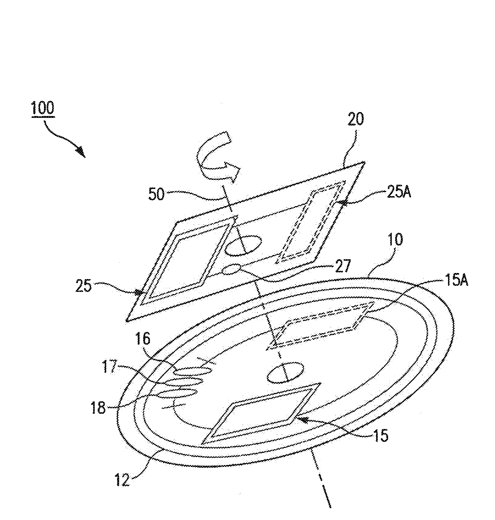
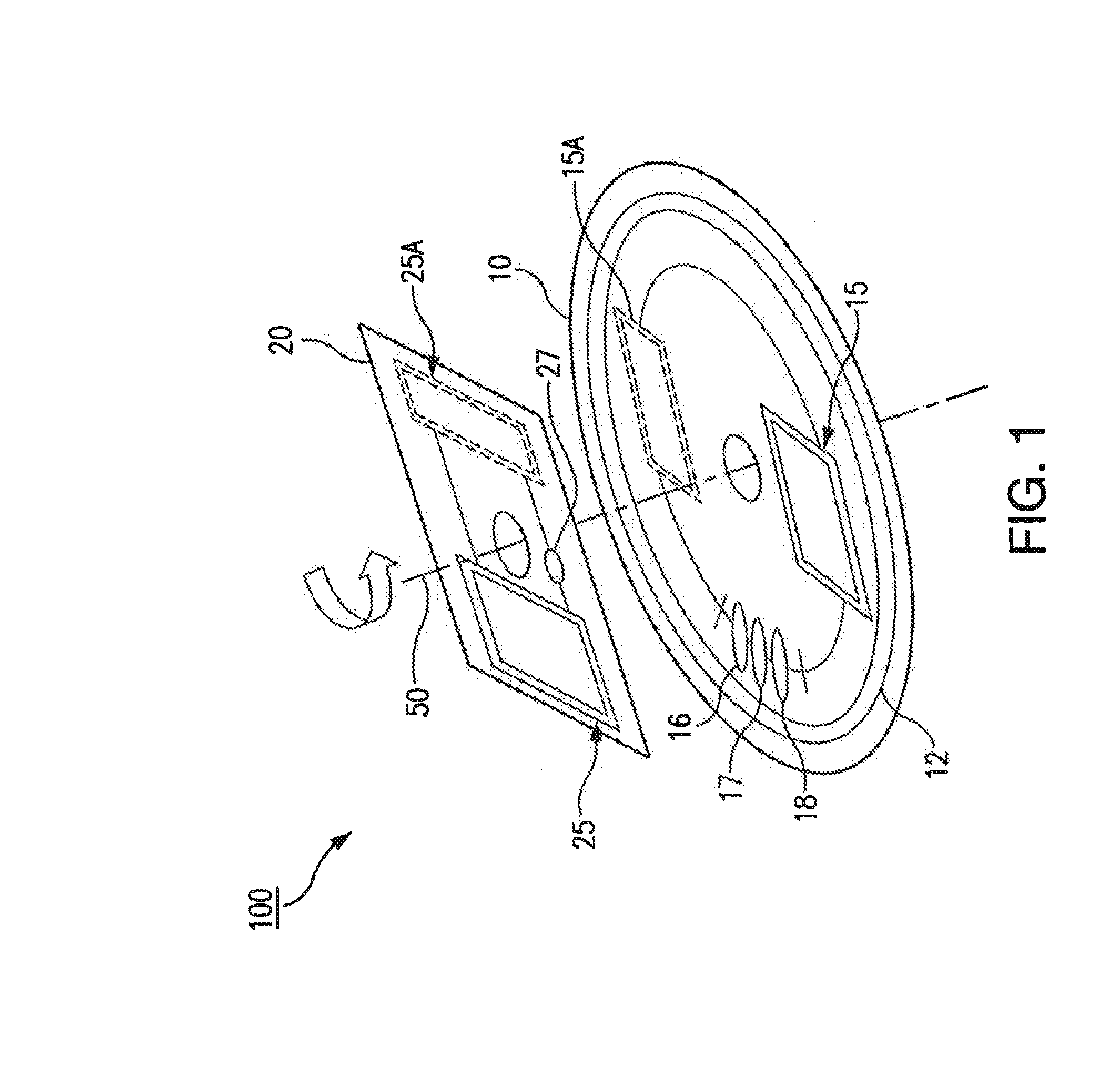
[0017]Reference will now be made to the drawings wherein like reference numerals identify similar structural features or aspects of the subject disclosure. For purposes of explanation and illustration, and not limitation, a partial view of an exemplary embodiment of the sensor assembly in accordance with the disclosure is shown in FIG. 1 and is designated generally by reference character 100. The systems and methods described herein can be used to provide a contactless rotational speed sensor using induction coupling and sensing.

[0018]Induction based rotational speed sensing in accordance with the disclosure can use electromagnetic coils made out of copper traces on a Printed Circuit Board (PCB). This sensor includes two adjacent PCBs separated by a nominally designed distance. The first PCB holds a high frequency electromagnetic field generator coil called the excitation or transmitter coil in addition to the sensing winding, also referred to as the receiver coil. The second PCB ho...


PUM


Abstract

An inductive rotational speed sensor assembly includes a first PCB with a transmitter coil configured to convert an alternating electrical input into an alternating magnetic field. A second PCB is operatively connected to the first PCB for relative rotation and includes a resonance coil configured to couple to the alternating magnetic field of the first PCB to output a modulating position signal. The first PCB includes a receiver coil configured to receive the first and the modulating position signal and to output a signal indicative of rotational speed of the second PCB relative to the first PCB.

Description

CROSS-REFERENCE TO RELATED APPLICATIONS[0001]This application claims priority to U.S. Provisional Patent Application No. 61 / 912,709 filed Dec. 6, 2013, which is incorporated by reference herein in its entirety.BACKGROUND OF THE INVENTION[0002]1. Field of the Invention[0003]The present disclosure relates to sensors, and more particularly to inductive contactless sensors for measuring rotational speed.[0004]2. Description of Related Art[0005]Induction-based sensor technology uses sensing coils that are made of copper traces printed on electronic printed circuit board. This type of sensor is capable of measuring the relative position between a sensing printed circuit and a position target without being in physical contact with it. This technology is outlined for various applications in U.S. Pat. Nos. 6,534,970 and 8,129,985, each of which is incorporated by reference in its entirety. This type of technology has been widely used for position sensing, but has not been often used to measu...

Claims


Application Information

Patent Timeline
11 Jun 2015
Publication
US20150160254A1
IPC
G01P3/48
CPC
G01P3/48; G01P3/488; G01D5/204
Inventors
HUYNH, CUONG T.; ESSAWY, MAGDI A.