Method and device for optimization of a pulse sequence for a magnetic resonance system

a magnetic resonance system and pulse sequence technology, applied in the direction of reradiation, measurement using nmr, instruments, etc., can solve the problems of affecting the performance of the gradient coil, so as to achieve the effect of less calculation time and small effor

Active Publication Date: 2015-06-11
SIEMENS HEALTHCARE GMBH
View PDF5 Cites 15 Cited by
  • Summary
  • Abstract
  • Description
  • Claims
  • Application Information

AI Technical Summary

Benefits of technology

[0010]An object of the present invention is to provide such a method and a corresponding pulse sequence optimization device for opt

Problems solved by technology

In particular, such a high edge steepness contributes to noise development during the switching of the gradients.
In addition to this, steep edges of the gradients lead to a higher power consumption and additionally place higher demands on the gradient coils and the additional hardware.
The rapidly changing gradient fields lead to distortions and oscillations in the gradient coils, and to the transfer of these energies to the housing.
A high helium boil-off

Method used


Image

  • Method and device for optimization of a pulse sequence for a magnetic resonance system
  • Method and device for optimization of a pulse sequence for a magnetic resonance system
  • Method and device for optimization of a pulse sequence for a magnetic resonance system

Examples


Embodiment Construction

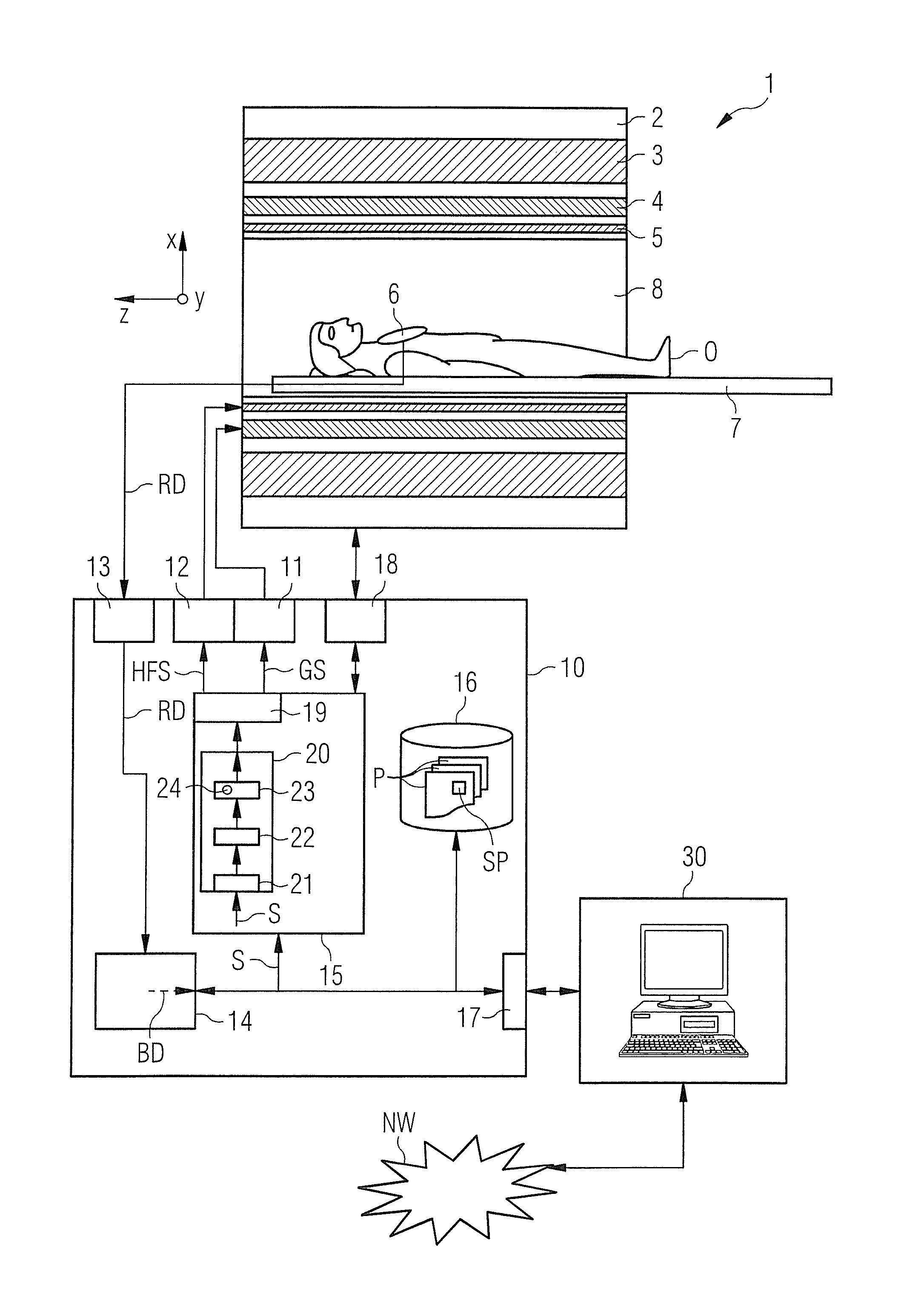
[0068]In the following, the invention is described in an example of an implementation in the pulse sequence optimization device or of a use within the optimization method as they are explained in detail as an exemplary embodiment in DE 10 2013 202 559. However, at this point it is explicitly noted that the invention can also be used in other forms, for example directly in the pulse design or, respectively, the original calculation or preparation of the pulse sequence.

[0069]Roughly schematically shown in FIG. 1 is a magnetic resonance system 1 set up according to the invention. On the one hand, it comprises the actual magnetic resonance scanner 2 with an examination space 8 or, respectively, patient tunnel 8 located therein. A bed 7 can be driven into this patient tunnel 8, such that a patient O or test subject lying on can be supported at a specific position within the magnetic resonance scanner 2 relative to the magnet system and radio-frequency system arranged therein or, respecti...


PUM


Abstract

In a method and a pulse sequence optimization device to determine a pulse sequence for a magnetic resonance system, a determination of a time interval in a pulse sequence that is to be optimized with regard to a gradient curve initially takes place, the pulse sequence including a number of radio-frequency pulses and a number of gradient pulses that are to be chronologically coordinated, under determination of the following boundary conditions for the gradient curve: length of the time interval, target integral of the gradient curve over the time interval, start value of the gradient curve at the beginning of the time interval, end value of the gradient curve at the end of the time interval. A gradient curve is then defined according to a function that is linear per segment by addition of a first linear function that connects the start value and the end value and a second function that is linear per segment that assumes a function value of “zero” at the beginning and end of the time interval, and that is defined so that the sum of the integral of the first linear function and of the integral of the second function corresponds to the target integral.

Description

BACKGROUND OF THE INVENTION[0001]1. Field of the Invention[0002]The invention concerns a method to optimize a pulse sequence for a magnetic resonance sequence. Moreover, the invention concerns a method to operate a magnetic resonance system using such an optimized pulse sequence, as well as a pulse sequence optimization device for a magnetic resonance system in order to implement such a method.[0003]2. Description of the Prior Art[0004]In a magnetic resonance system (also called a magnetic resonance tomography system), the body to be examined is typically exposed to a relatively high basic magnetic field—for example of 1, 5, 3 or 7 Tesla—by operation of a basic field magnet system, which often contains superconducting coils. A magnetic field gradient is additionally applied with the aid of a gradient system. Radio-frequency excitation signals (RF signals) are then emitted via a radio-frequency transmission system, which leads to the situation that the nuclear spins of specific atoms...

Claims


Application Information

Patent Timeline
IPC IPC(8): G01R33/54
CPCG01R33/546G01R33/543
Inventor GRODZKI, DAVID
Owner SIEMENS HEALTHCARE GMBH
Why Eureka
Try Eureka