Tomography system

a tomography system and imaging technology, applied in tomography, instruments, applications, etc., can solve the problems of inability to deal with density non-uniformity (luminescence non-uniformity), lack of accuracy, and various artifacts, and achieve the effect of reducing artifacts

Active Publication Date: 2015-06-18
KONICA MINOLTA INC
View PDF0 Cites 9 Cited by
  • Summary
  • Abstract
  • Description
  • Claims
  • Application Information

AI Technical Summary

Benefits of technology

[0008]Objects of the present invention include to minimize artifacts which appear in a

Problems solved by technology

However, in the tomograms obtained by reconstruction using the projection images obtained by tomosynthesis imaging, various artifacts appear.
Further, the art described in Patent Document 2 is applicable to any of these methods but cannot deal with the case where density non-uni

Method used


Image

  • Tomography system
  • Tomography system
  • Tomography system

Examples


first embodiment

Configuration of Tomography System 100

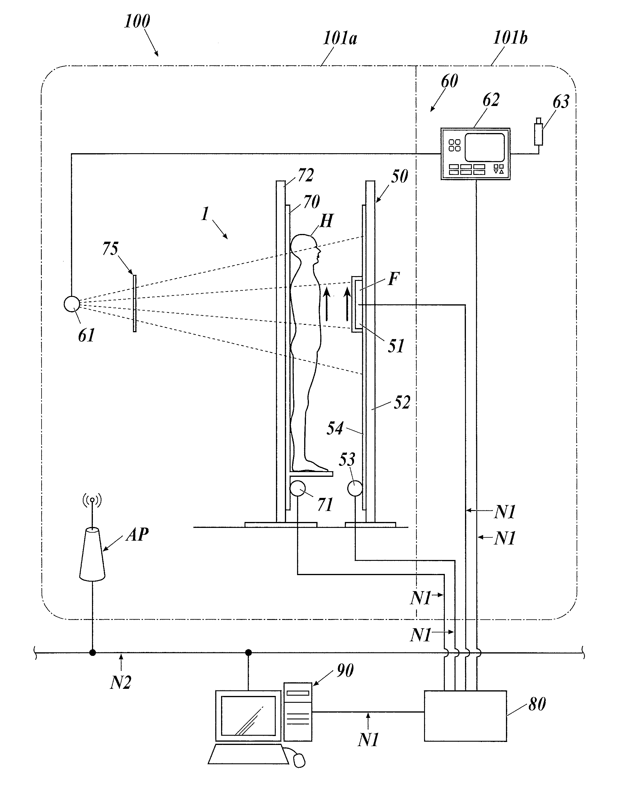
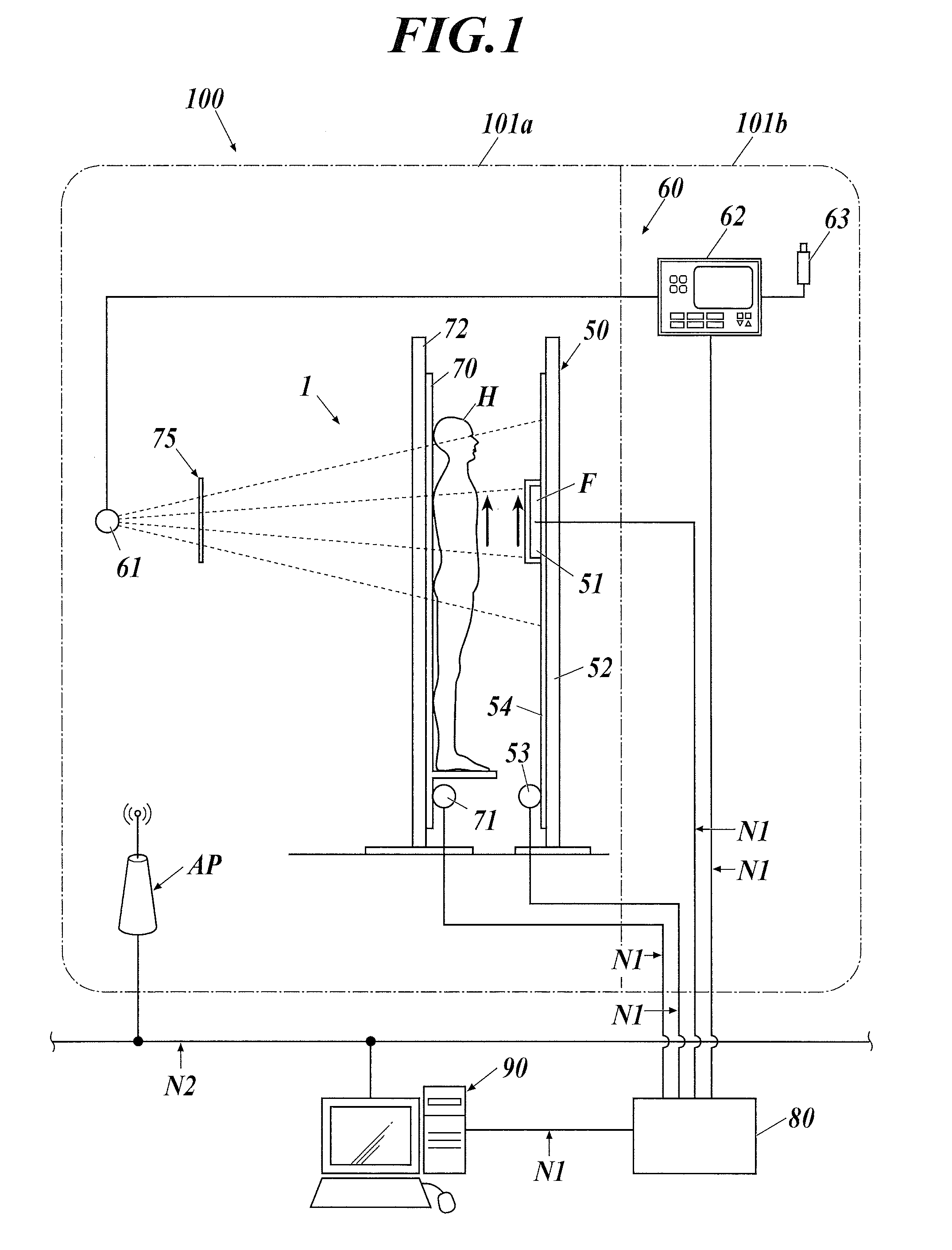
[0025]First, a schematic configuration of a tomography system according to a first embodiment of the present invention is described. A tomography system 100 is a system to generate each diagnostic tomogram with projection images obtained with tomosynthesis imaging of a subject H (a site of a human body). FIG. 1 shows a schematic configuration of the tomography system 100 according to the embodiment. As shown in FIG. 1, the tomography system 100 is mainly constituted of: a tomography device 1 including a radiation detector F; and a console 90.

[0026]The tomography system 100 is provided inside and outside an imaging room 101a and a front room (also called an operation room or the like) 101b. In the imaging room 101a, an imaging table 50, a radiation source 61 and the like of the tomography device 1 are disposed. In the imaging room 101a, an access point AP to rely wireless communication between the radiation detector F and the console 90 described...

second embodiment

[0073]Next, a second embodiment of the present invention is described.

[0074]The configuration of the tomography system 100 in the second embodiment is the same as that thereof described in the first embodiment, and therefore description thereof is omitted here, and action thereof in the second embodiment is described hereinafter.

[0075]In the second embodiment, first, in the tomography device 1, imaging is performed a predetermined number of times while the radiation detector F and the subject table 70 are moved in relation to the radiation source 61 in a state in which a subject H is on the subject table 70, whereby a series of subject-included projection images are generated and sent to the console 90.

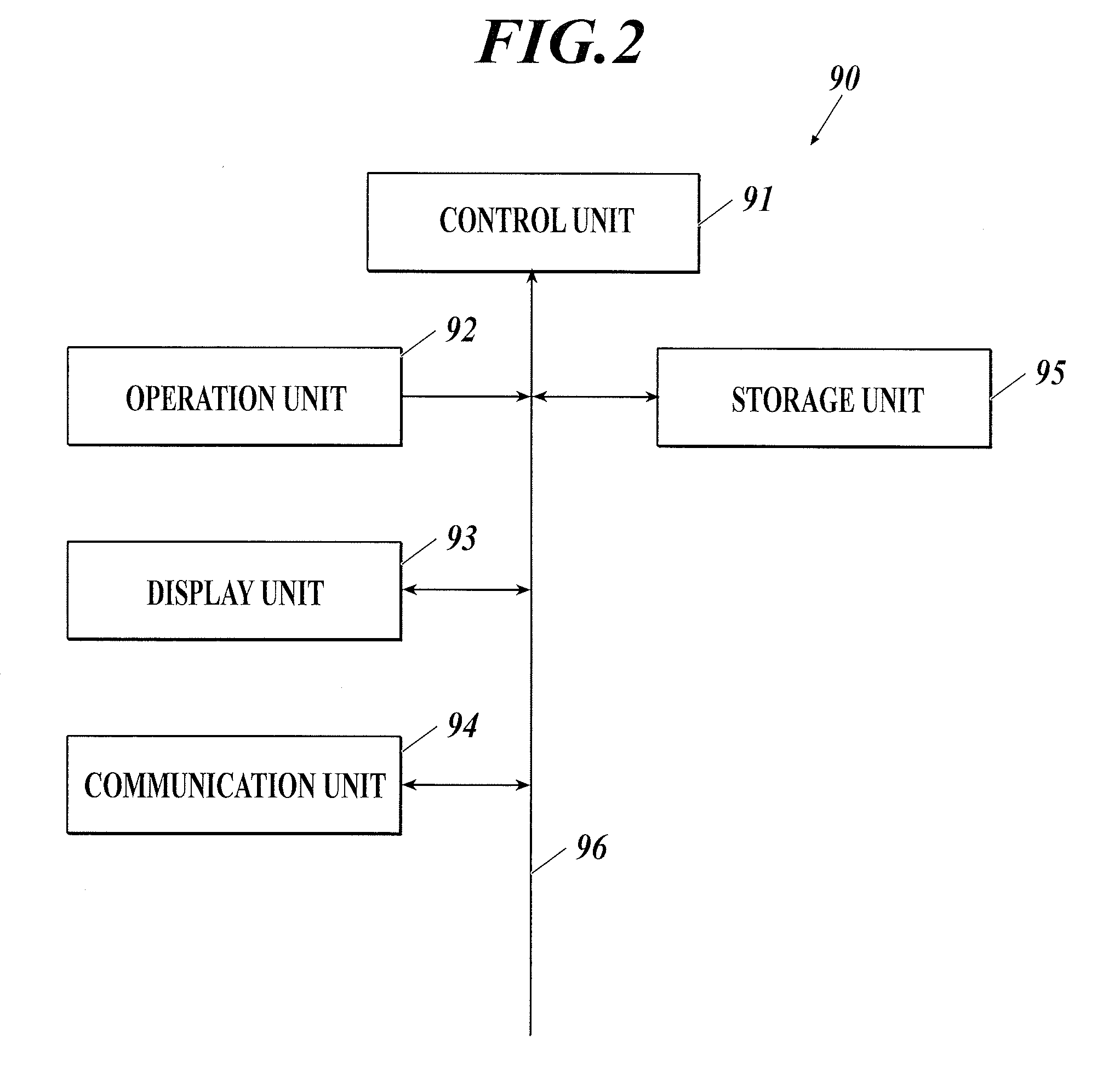
[0076]When receiving the projection images via the communication unit 94, the control unit 91 of the console 90 performs reconstructed image generation processing B on the basis of the received projection images.

[0077]FIG. 6 is a flowchart of the reconstructed image generation process...

third embodiment

[0092]Next, a third embodiment of the present invention is described.

[0093]The configuration of the tomography system 100 in the third embodiment is the same as that thereof described in the first embodiment, and therefore description thereof is omitted here, and action thereof in the third embodiment is described hereinafter.

[0094]In the tomography system 100 in the third embodiment, a reconstructed image is generated with the successive approximation image reconstruction method. For that, the console 90 performs reconstructed image generation processing C, thereby creating a profile of each no-subject-included projection image or each subject-included projection image sent from the tomography device 1; correcting, on the basis of the created profile, a detection probability (detection probabilities) used in image reconstruction with the successive approximation image reconstruction method; and generating a tomogram, which is a reconstructed image, with the successive approximation...


PUM


Abstract

A tomography system includes a radiation source, a radiation detector, a subject table, an imaging unit and a reconstruction unit. The imaging unit obtains a projection image a predetermined number of times while changing a positional relationship of the radiation source and the radiation detector. The reconstruction unit generates a tomogram of a subject using the projection image obtained by the imaging unit. The reconstruction unit includes a correction unit. The correction unit performs correction processing to (i) create a profile of a pixel signal value from a no-subject-included projection image obtained by the imaging unit without the subject on the subject table and (ii) correct, on the basis of the created profile, a subject-included projection image obtained by the imaging unit with the subject on the subject table or a detection probability used in generating the tomogram.

Description

CROSS REFERENCE TO PRIOR ART[0001]The present invention claims priority under 35 U.S.C. §119 to Japanese Application No. 2013-260756 filed Dec. 18, 2013, the entire content of which is incorporated herein by reference.FIELD OF THE INVENTION[0002]The present invention relates to a tomography system.DESCRIPTION OF THE RELATED ART[0003]In recent years, there has been used in the field of medical services a tomography device which performs tomosynthesis imaging, thereby emitting radiation to the body of a patient as a subject from around the body, converting the radiation having passing through the subject into electric signals and obtaining the electric signals as projection images. An image processing device performs reconstruction using the projection images of the subject obtained by the tomography device, thereby generating two-dimensional tomograms at predetermined cross sections of the subject.[0004]However, in the tomograms obtained by reconstruction using the projection images ...

Claims


Application Information

Patent Timeline
IPC IPC(8): A61B6/00A61B6/02
CPCA61B6/025A61B6/5258A61B6/032A61B6/5205A61B6/585
Inventor YAMAMURA, TAKUYAONO, YOUICHIKANAMORI, KOUTAROU
Owner KONICA MINOLTA INC
Why Eureka
Try Eureka