This helps you quickly interpret patents by identifying the three key elements:
Problems solved by technology
Method used
Benefits of technology
Benefits of technology
The invention provides a simple and affordable solar power system that can maintain high efficiency even after extended usage. This system can be constructed without advanced technology or skilled labor, making it an ideal solution for low-income or emergency situations.
Problems solved by technology
In the case where a solar power system is used to generate electric power, there may be a case where working fluid for driving a steam turbine cannot be heated sufficiently only by solar heat obtained at that time due to the variation or decrease of the amount of solar radiation.
Method used
Image
Click on the blue label to locate the original text in one second.
Reading with bidirectional positioning of images and text.
Examples
first embodiment
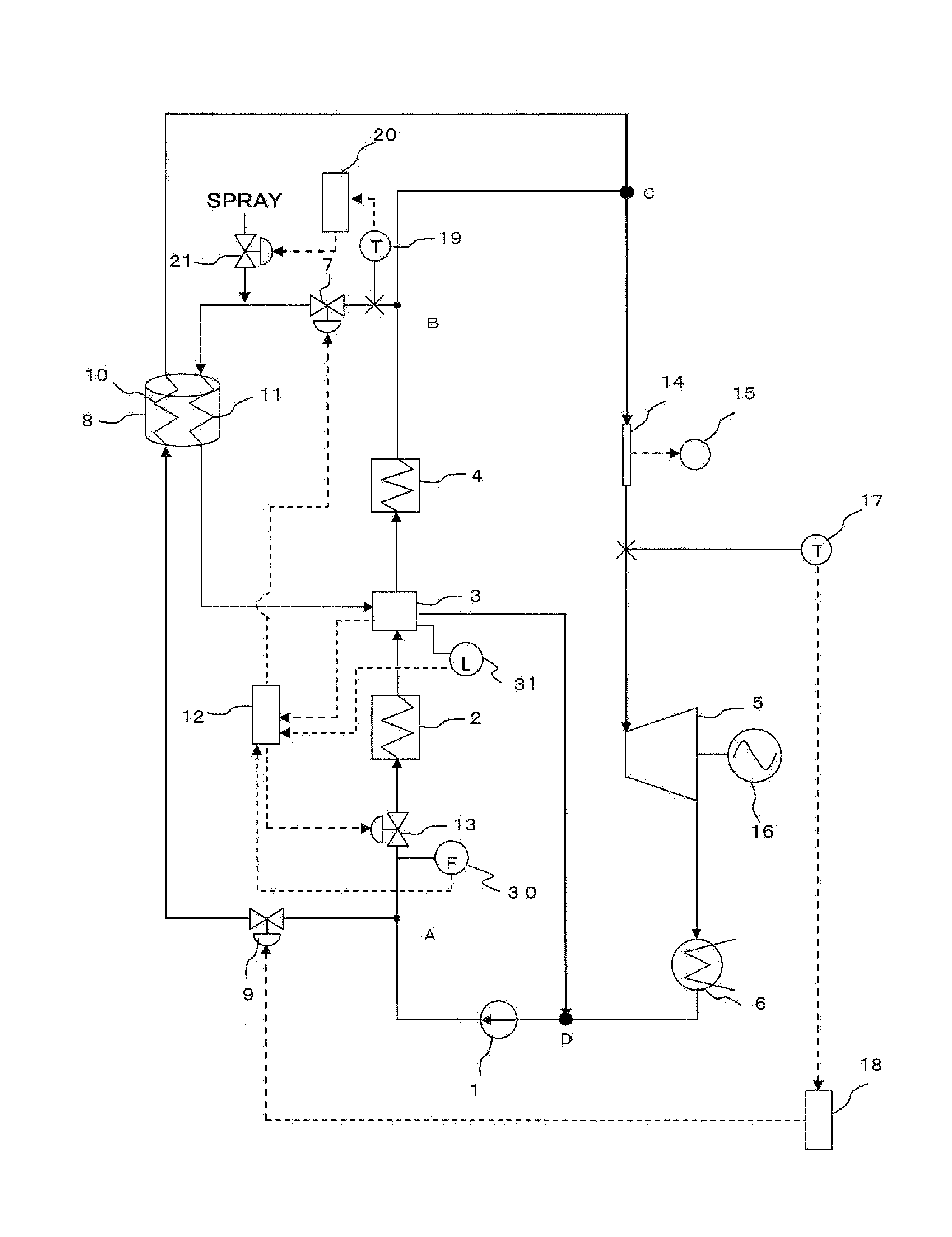
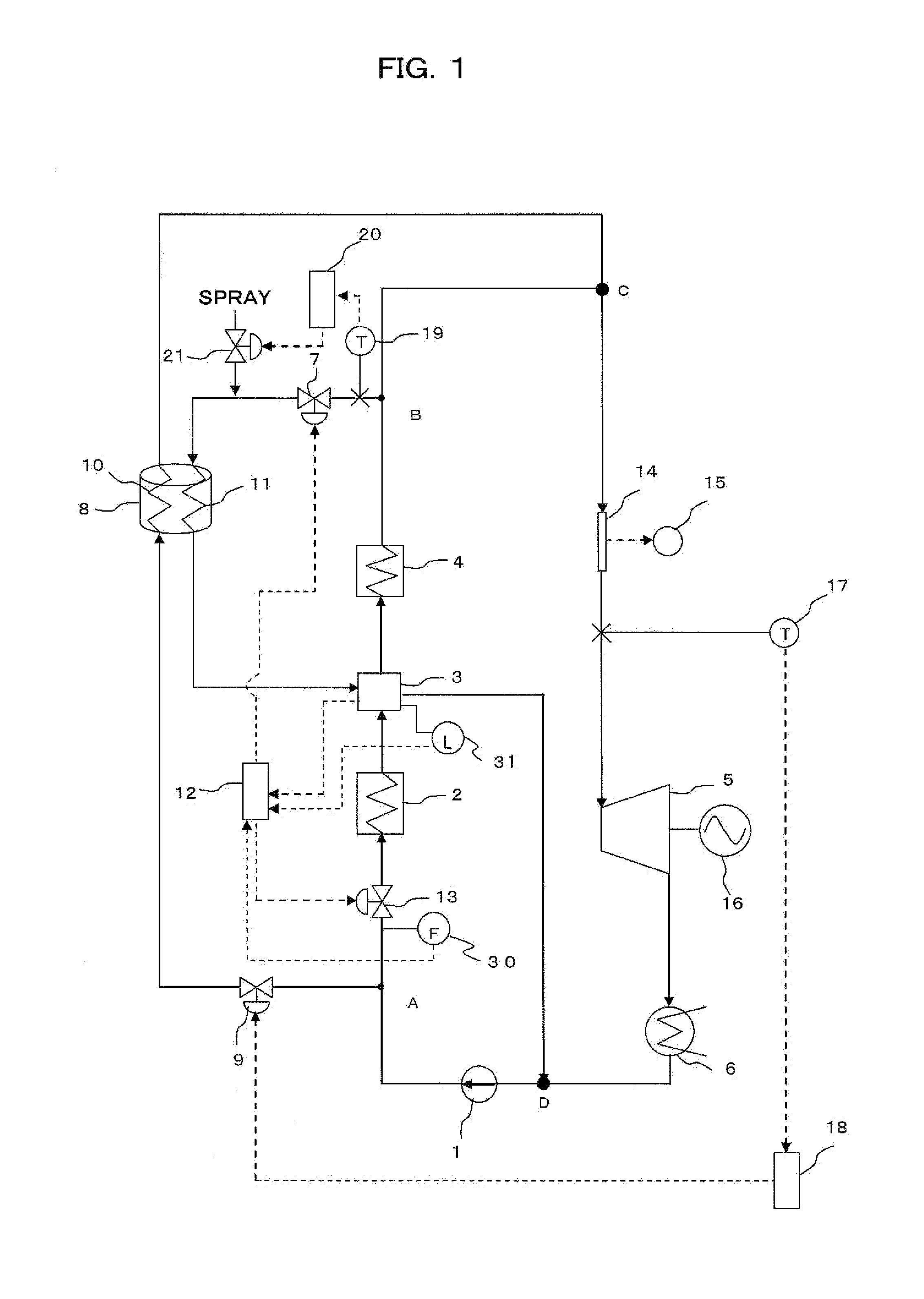
[0063]FIG. 1 is a view of the configuration of a solar power system according to an embodiment of the invention. In the drawing, the reference numeral 1 designates a feedwater pump; 2, a low temperature heat collection device (heat collection apparatus) which collects sunlight to heat water; 3, a steam-water separation device; 4, a high temperature heat collection device (heat collection apparatus) which collects sunlight to heat steam; 5, a steam turbine; 6, a gland condenser; 7, a steam extraction valve; 8, a heat storage device; 9 and 13, water supply valves; 10, a water supply heat transferpipe; 11, a superheated steam heat transferpipe; 12, an arithmetic device (second control device); 14, a flowmeter; 15, a flow rate display panel; 16, a power generator; 17, a thermometer; 18, an arithmetic device; 19, a thermometer (temperature detector); 20, an arithmetic device (first control device); 21, a spray valve; 30, a flowmeter (flow rate detector) which measures the flow rate of ...
second embodiment
[0088]FIG. 3 is a view of the configuration of a solar power system according to a second embodiment of the invention. In the drawing, the reference numeral 1 designates a feedwater pump; 2, a low temperature heat collection device; 3, a steam-water separation device; 4, a high temperature heat collection device; 5, a steam turbine; 6, a gland condenser; 16, a power generator; 38, a medium circulation pump; 39, a main circulation pump; 41, a main steam valve; 42a to 42e, changeover valves; 43; a flow rate regulation valve; 45, a feedwater heater; 46, a tank; 51, a high temperature heat storage device; and 60, a deaerator which reduces or removes dissolved oxygen in supplied water.
[0089]A line 6-2 which is formed to connect the gland condenser 6, the deaerator 60, the feedwater pump 1, the feedwater heater 45, the tank 46, the main circulation pump 39, and the low temperature heat collection device 2 corresponds to a “water supply line” which supplies water to the low temperature hea...
third embodiment
[0098]FIG. 6 is a view of the configuration of a solar power system according to a third embodiment of the invention. The solar power system according to the third embodiment is characterized in that a Fresnel type light / heat collection device is used as the low temperature heat collection device 2 and a tower type light / heat collection device is used as the high temperature heat collection device 4 in comparison with the configuration of the solar power system according to the second embodiment. However, the remaining configuration of the solar power system according to the third embodiment is the same as that in the second embodiment. Therefore, duplicate description thereof will be omitted.
[0099]In the tower type light / heat collection device shown in FIG. 6, a heat transferpipe panel 72 is installed on a tower 71 having a predetermined height (about 30 m to 100 m). On the other hand, a large number of heliostats 70 are disposed in various directions on the ground surface. While ...
PUM
Abstract
Provided is an inexpensive and simple solar powersystem. A solar powersystem according to the present invention includes: a heat collection apparatus (2, 4); a steam turbine (5), a power generator (16); a superheated steam supply line which supplies the steam turbine with superheated steam generated by the heat collection apparatus; a water supply line which condenses the steam expelled from the steam turbine into water and supplies the condensed water to the heat collection apparatus; a heat storage device (8) which has a heat storage medium; a first line which branches from the superheated steam supply line and which supplies the heat storage device with the superheated steam flowing through the superheated steam supply line; a second line which branches from the water supply line and which supplies the heat storage device with the water flowing through the water supply line; and a third line which supplies the steam turbine with superheated steam generated by the heat storage device. The heat storage device stores the heat of the superheated steam which has flowed through the first line in the heat storage medium, and heats the water which has flowed through the second line with the heat storage medium to thereby generate the superheated steam.
Description
TECHNICAL FIELD[0001]The present invention relates to a solar powersystem which can collect solar heat, generate steam with the heat, and drive a steam turbine with the steam to thereby generate electric power.BACKGROUND ART[0002]In the case where a solar power system is used to generate electric power, there may be a case where working fluid for driving a steam turbine cannot be heated sufficiently only by solar heat obtained at that time due to the variation or decrease of the amount of solar radiation. To solve this problem, in many examples, a heat storage device is incorporated in the solar power system and heat collected by a heat collection device is stored in advance in the heat storage device so that the stored heat can be extracted and used if necessary (Patent Literatures 1 to 4).CITATION LISTPatent Literature[0003]Patent Literature 1: JP-A-60-122865[0004]Patent Literature 2: U.S. Pat. No. 7,296,410[0005]Patent Literature 3: U.S. Pat. No. 8,087,245[0006]Patent Literature...
Claims
Application Information
Patent Timeline
Application Date:The date an application was filed.
Publication Date:The date a patent or application was officially published.
First Publication Date:The earliest publication date of a patent with the same application number.
Issue Date:Publication date of the patent grant document.
PCT Entry Date:The Entry date of PCT National Phase.
Estimated Expiry Date:The statutory expiry date of a patent right according to the Patent Law, and it is the longest term of protection that the patent right can achieve without the termination of the patent right due to other reasons(Term extension factor has been taken into account ).
Invalid Date:Actual expiry date is based on effective date or publication date of legal transaction data of invalid patent.

