Power system of lifting device and control method thereof

A lifting device, power system technology, applied in the direction of lifting device, fluid pressure actuation system components, pump device, etc., can solve the problem of low motor energy recovery efficiency, and achieve high driving efficiency, high driving efficiency and high power generation efficiency. Effect

Active Publication Date: 2018-12-11
NORTH VALLEY ELECTRONICS CO LTD
View PDF2 Cites 0 Cited by
  • Summary
  • Abstract
  • Description
  • Claims
  • Application Information

AI Technical Summary

Problems solved by technology

[0005] The purpose of the present invention is to provide a lifting device power system and its control method to solve the problem of low energy recovery efficiency of existing motors

Method used


Image

  • Power system of lifting device and control method thereof
  • Power system of lifting device and control method thereof
  • Power system of lifting device and control method thereof

Examples


Embodiment 1

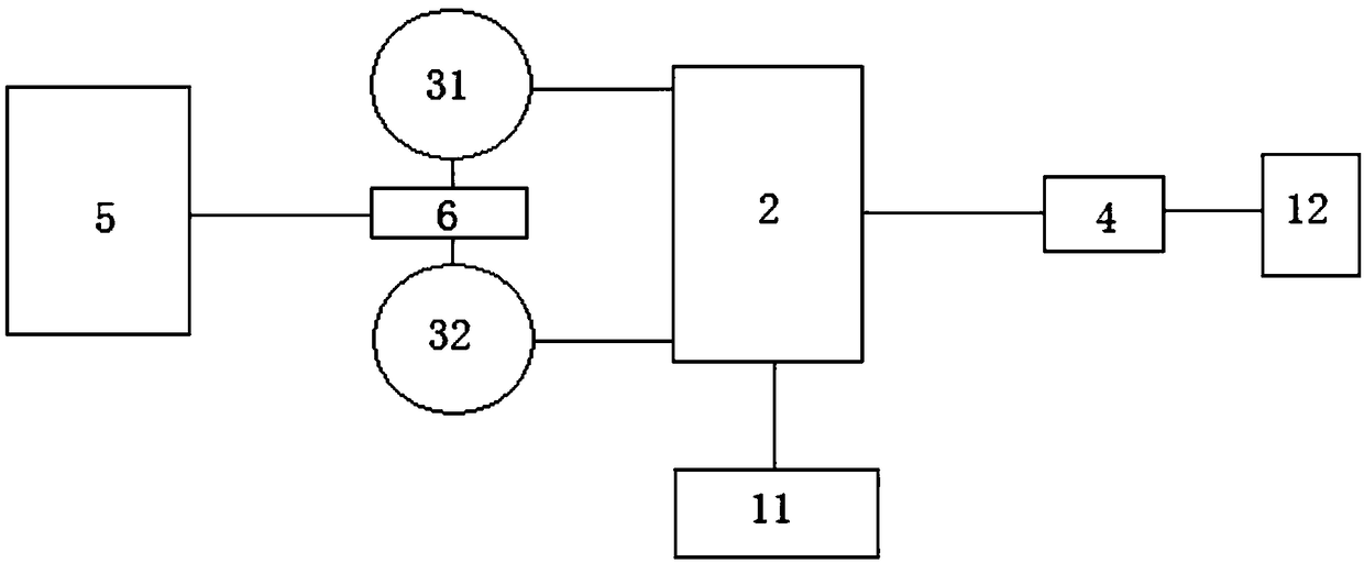
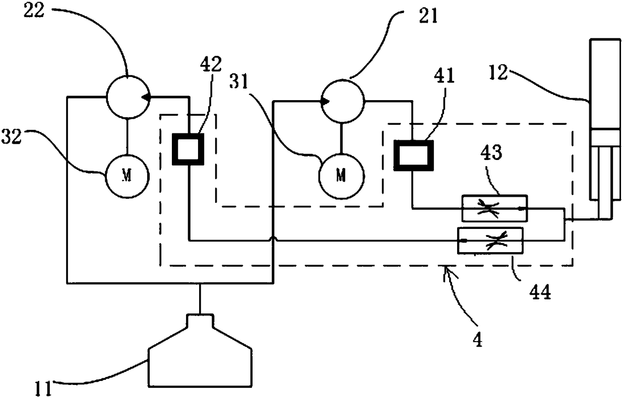
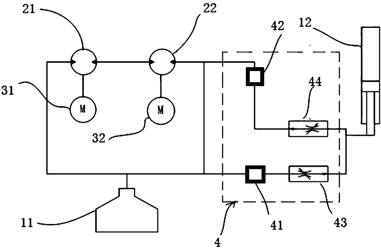
[0045] This embodiment provides a lifting device power system, such as figure 1 As shown, the lifting device power system drives a lifting device to rise and fall, and the lifting device power system includes a hydraulic cylinder 12, a liquid delivery system 4, a battery system 5, a motor control unit 6, a first motor 31, a second motor 32. The hydraulic pump system 2 and the liquid storage tank 11, wherein: when the lifting device rises, the battery system 5 supplies power to the first motor 31 through the motor control unit 6, and the first motor 31 drives the The hydraulic pump system 2 rotates, the hydraulic pump system 2 draws fluid from the reservoir 11 and supplies it to the fluid delivery system 4 which supplies the fluid to the hydraulic cylinder 12 to increase the pressure of the liquid in the hydraulic cylinder 12, and the hydraulic cylinder 12 converts hydraulic energy into mechanical energy to drive the lifting device to rise; when the lifting device descends, th...

Embodiment 2

[0064] This embodiment provides a control method for the power system of the lifting device, including: figure 1 As shown, a lifting device is driven up and down by the power system of the lifting device, wherein: when the lifting device rises, the battery system 5 supplies power to the first motor 31 through the motor control unit 6, and the first motor 31 drives the hydraulic pump The system 2 rotates, the hydraulic pump system 2 draws fluid from the reservoir 11, and supplies it to the fluid delivery system 4, which supplies the fluid to the hydraulic cylinder 12, so that the hydraulic cylinder 12 The pressure of the liquid in the lifting device rises, and the hydraulic cylinder 12 converts the hydraulic energy into mechanical energy, driving the lifting device to rise; when the lifting device descends, the mechanical energy of the power system of the lifting device is converted into hydraulic energy, and the hydraulic pressure The liquid in the cylinder 12 automatically f...


PUM


Abstract

The invention provides a power system of a lifting device and a control method thereof. When the lifting device rises, a battery system supplies power to a first motor, the first motor drives a hydraulic pump system to rotate, the hydraulic pump system extracts liquid from a liquid storage tank and supplies the liquid to a liquid conveying system, the liquid conveying system supplies the liquid toa hydraulic cylinder, and the hydraulic cylinder converts hydraulic energy into mechanical energy to drive the lifting device to rise; and when the lifting device descends, the mechanical energy of the power system of the lifting device is converted into the hydraulic energy, so that the liquid in the hydraulic cylinder flows to the liquid conveying system, the liquid flows to the hydraulic pumpsystem through the liquid conveying system and drives the hydraulic pump system to rotate, the hydraulic pump system drives a second motor to rotate, the second motor generates electricity and supplies generated electric energy to the battery system, and therefore the battery system is charged.

Description

technical field [0001] The invention relates to the technical field of lifting devices, in particular to a power system of a lifting device and a control method thereof. Background technique [0002] Aerial work vehicles have a wide range of applications. Usually, aerial work vehicles include a boom set on the car body and a working bucket or working device installed at the end of the boom. The staff enters the working bucket and uses the boom to move The working bucket and the staff or the working device are sent to a high place for high-altitude operations. In the hydraulic system of the existing aerial work vehicle, when the aerial work vehicle descends at a high place, the speed of the descent is controlled by the throttle valve, causing most of the potential energy released during the descent to be consumed on the throttle valve, and the potential energy is transformed into For the heat energy of the hydraulic system and the temperature rise of the oil in the system, i...

Claims


Application Information

Patent Timeline
Patent Type & Authority Applications(China)
IPC IPC(8): B66F11/04F15B11/08
CPCB66F9/22F15B21/14B66F11/04F15B11/08B66F2700/09F04B17/03F15B2211/20515F15B2211/20569F15B2211/20576F15B2211/2658F15B2211/7052F15B2211/7058F15B2211/761F04B23/02
Inventor 周斌欣张善睿邓波张琳
Owner NORTH VALLEY ELECTRONICS CO LTD
Why Eureka
Try Eureka