Motor with linear actuators

a linear actuator and motor technology, applied in the direction of flexible wall reciprocating engines, electrical devices, belts/chains/gearings, etc., can solve the problems of reducing the scalability of the motor, increasing the complexity of the motor, and affecting the operation, so as to achieve the effect of high efficiency and relative cost effectiveness

Inactive Publication Date: 2015-06-18
PHI DRIVE
View PDF8 Cites 19 Cited by
  • Summary
  • Abstract
  • Description
  • Claims
  • Application Information

AI Technical Summary

Benefits of technology

[0018]The object of the present invention is to overcome the above drawbacks, by providing

Problems solved by technology

A first drawback of this arrangement is that the provision of an intermediate element or the elliptical flexible bearing considerably increases the complexity of the motor.
This is an apparent restriction to scalability of the motor, as it would require the intermediate member to have a low ellipticity, and involve operational difficulties, because of the strict tolerances imposed thereupon.
Furthermore, the high accuracy required in the fabricati

Method used


Image

  • Motor with linear actuators
  • Motor with linear actuators
  • Motor with linear actuators

Examples


Embodiment Construction

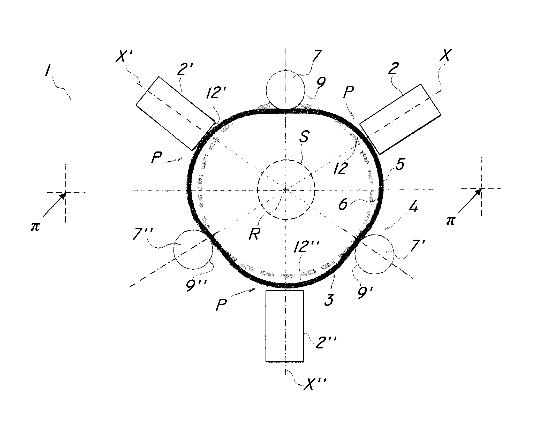
[0033]FIG. 1 is a schematic view of a first preferred, non-limiting configuration of a motor of the invention, generally designated by numeral 1.

[0034]The motor 1 is designed to be connected to a drive shaft S, as schematically shown herein, which may in turn be connected to a load, not shown, for high-accuracy motion thereof.

[0035]Particularly, the motor 1 of the invention is designed for use in electrical or electromechanical apparatus requiring light-weight loads to be moved at relatively high speeds and with relatively high accuracy. For example, the motor 1 may be used in the fields of electronic devices, precision-mechanics, instrumentation or other equivalent fields.

[0036]Nevertheless, as explained hereinbelow, the motor 1 has features that allow scalability, both in terms of scale increase and reduction, such that it can be also used for moving relatively heavy loads, that require delivery of a relatively high torque.

[0037]The motor 1 basically comprises a base plane π, in w...


PUM


Abstract

A motor powered by linear actuators comprises a base plane in which a plurality of linear actuators (2, 2′, 2″, 20) operate by reciprocating along respective lines of action (X, X′, X″), an elastic conversion member (3, 30) which is adapted to move in the plane and suitable to be connected to a drive shaft (S). The linear actuators (2, 2′, 2″, 20) are operatively connected with the conversion member (3, 30) for converting the reciprocating motion of the linear actuators (2, 2′,2″, 20) into a substantially continuous motion of the conversion member (3, 30). The motor also comprises stationary constraint means (4, 40) which are adapted to selectively interact with the conversion member (3, 30) to locally deform it and/or promote sliding and movement thereof the plane about a predetermined axis or in a predetermined direction in response to the action of the linear actuators (2, 2′, 2″, 20).

Description

FIELD OF THE INVENTION[0001]The present invention generally finds application in the field of energy conversion machines and particularly relates to a motor powered by the movement of linear actuators.BACKGROUND ART[0002]Motors are known which are designed to accomplish the motion of a load from an electric, pneumatic, oil-hydraulic or other source of energy.[0003]Particularly, motors are known which comprise a plurality of actuators designed for interaction with a rotary or linear moving member, by interaction with an elastic member operatively connected to the moving member, to promote rotation or translation thereof.[0004]The synchronized action of the actuators on the elastic member will cause local deformation thereof, such that the moving member may receive the driving force required to accomplish its motion.[0005]For example, U.S. Pat. No. 5,068,565 discloses a motor that comprises, in a particular configuration, a substantially annular motion transfer member, which is adapte...

Claims


Application Information

Patent Timeline
IPC IPC(8): F16H35/18H02N2/10F01B19/04
CPCF16H35/18H02N2/105F01B19/04F16H49/001H02N2/021Y10T74/18056
Inventor BONFIGLIO, PAOLOCAU, NICOLA LUSSORIO
Owner PHI DRIVE
Why Eureka
Try Eureka