High volume loading and stacking apparatus and method

a technology of high-volume excavating and stacking, applied in the direction of loading/unloading, soil shifting machines/dredgers, construction, etc., can solve the problems of reducing the efficiency of operation, reducing the efficiency of shovel operation, and high cost of operating large electric or hydraulic shovels, so as to eliminate the operator

Active Publication Date: 2015-06-25
LOWERY STERLING WAYNE
View PDF9 Cites 11 Cited by
  • Summary
  • Abstract
  • Description
  • Claims
  • Application Information

AI Technical Summary

Benefits of technology

[0010]A first object of the invention is to provide a loading and stacking apparatus that does not require an excavator to pull ore to the machine. The stacking and loading apparatus of the current invention utilizes a conventional dozer to charge the machine, with the dozer pushing material to the apron and the stacker conveyor continuously transporting the material from the apron to a truck or similar vehicle.
[0011]A second object of the invention is to eliminate the need for a feed conveyor. The stacker conveyor of the present invention uses only one conveyor to transport and convey material from the intake end to the discharge end.
[0012]A further object is to utilized double-hinged feeder blades, including a main blade and a wing blade, to continuously feed material from the apron to a waiting truck or similar vehicle. After the dozer pushes material onto the receiving area, the blades close staggered to completely clear the front apron of each pass.
[0013]A further object is to provide a loading and stacking apparatus that...

Problems solved by technology

Although this production rate is impressive, the efficiency of the shovel is limited by the dead time that occurs with each loading cycle of a truck.
The truck is therefore sitting idle for much of the time while the operator runs through his loading cycle and this reduces the efficiency of the o...

Method used


Image

  • High volume loading and stacking apparatus and method
  • High volume loading and stacking apparatus and method
  • High volume loading and stacking apparatus and method

Examples


first embodiment

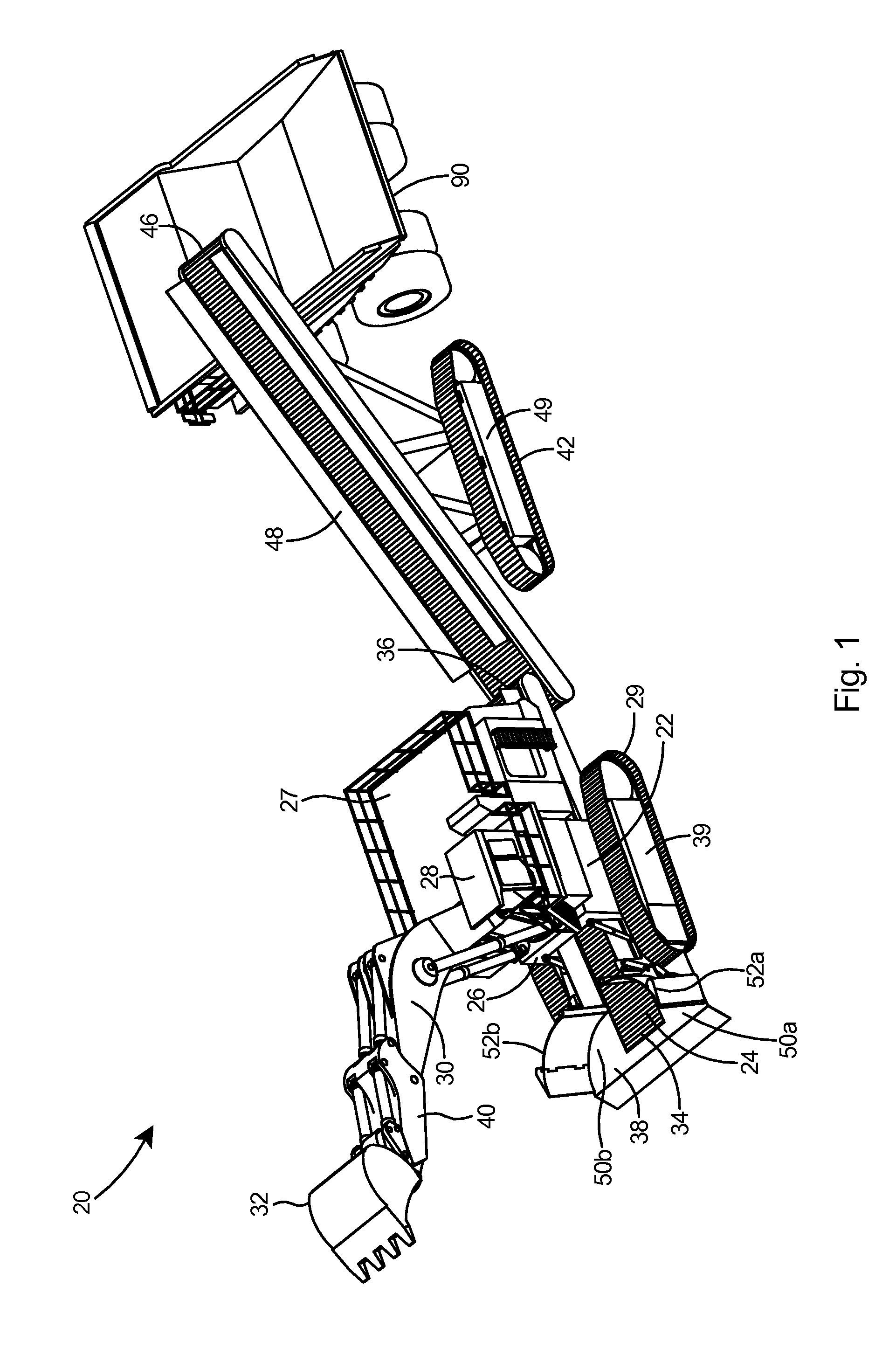
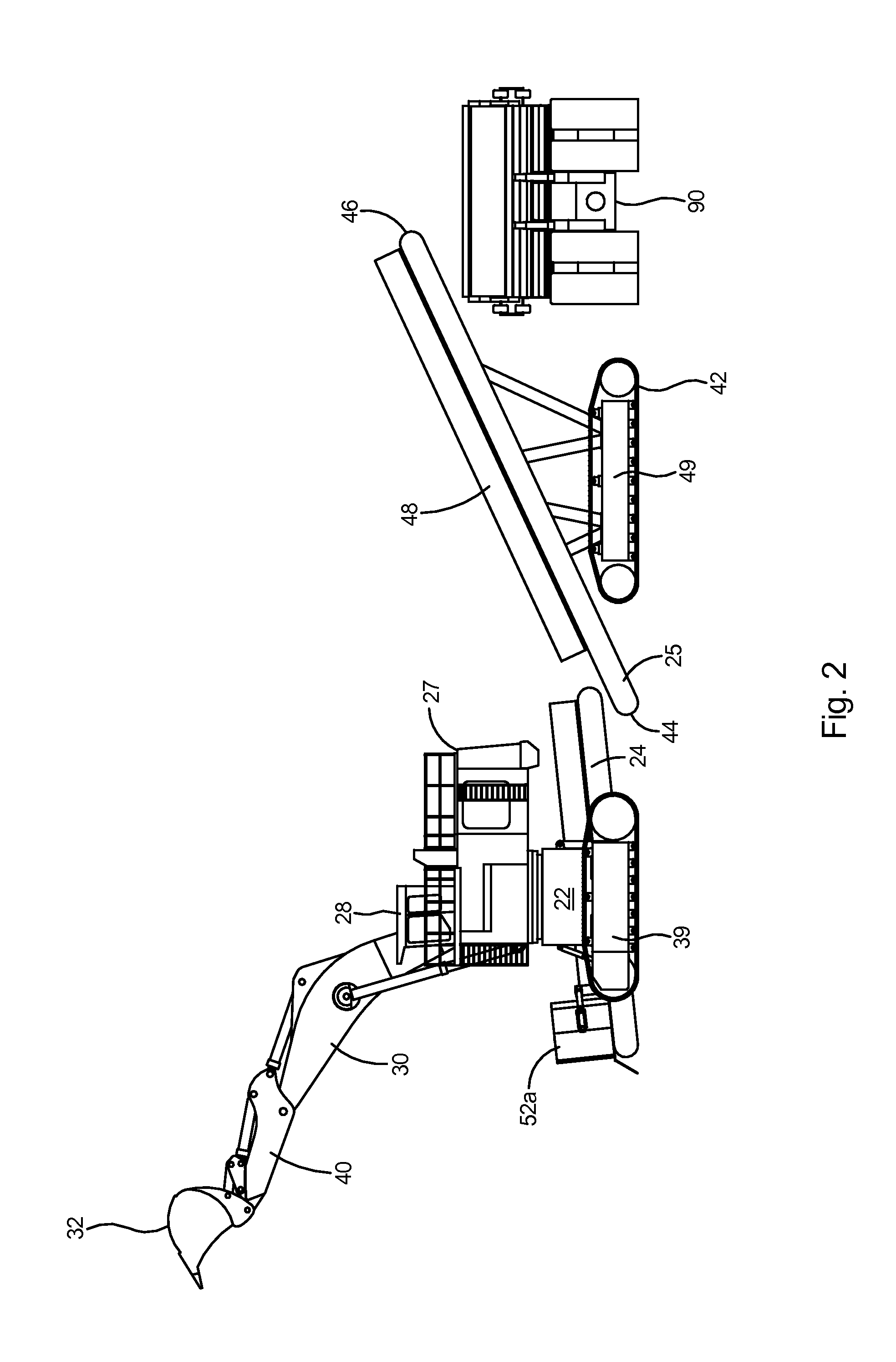
[0041]With reference to FIG. 1 there is shown an excavating and loading apparatus 20 according to the present invention. The excavating and loading apparatus 20 includes an excavator 22, a feeder conveyor 24, and a stacker conveyor 25. The excavator 22 includes a front end 26, an upper stage 27 that includes a control station 28, paired crawler tracks 29, and an articulated boom 30 with a bucket 32. The feeder conveyor 24 is pinned beneath the upper stage 27 and includes an intake end 34 and a discharge end 36. A wide apron 38 is positioned at the intake end 34 of the feeder conveyor 24. The paired crawler tracks 29 of the excavator are supported by a crawler frame 39.

[0042]Referring to FIG. 2, the excavator 22 is connected to bucket 32 by articulated boom 30 and stick 40. The stacker conveyor 25 is on paired crawler tracks 42 and includes an intake end 44, a discharge end 46, and side walls 48 for containing material on the stacker conveyor. The paired crawler tracks 42 of the stac...

second embodiment

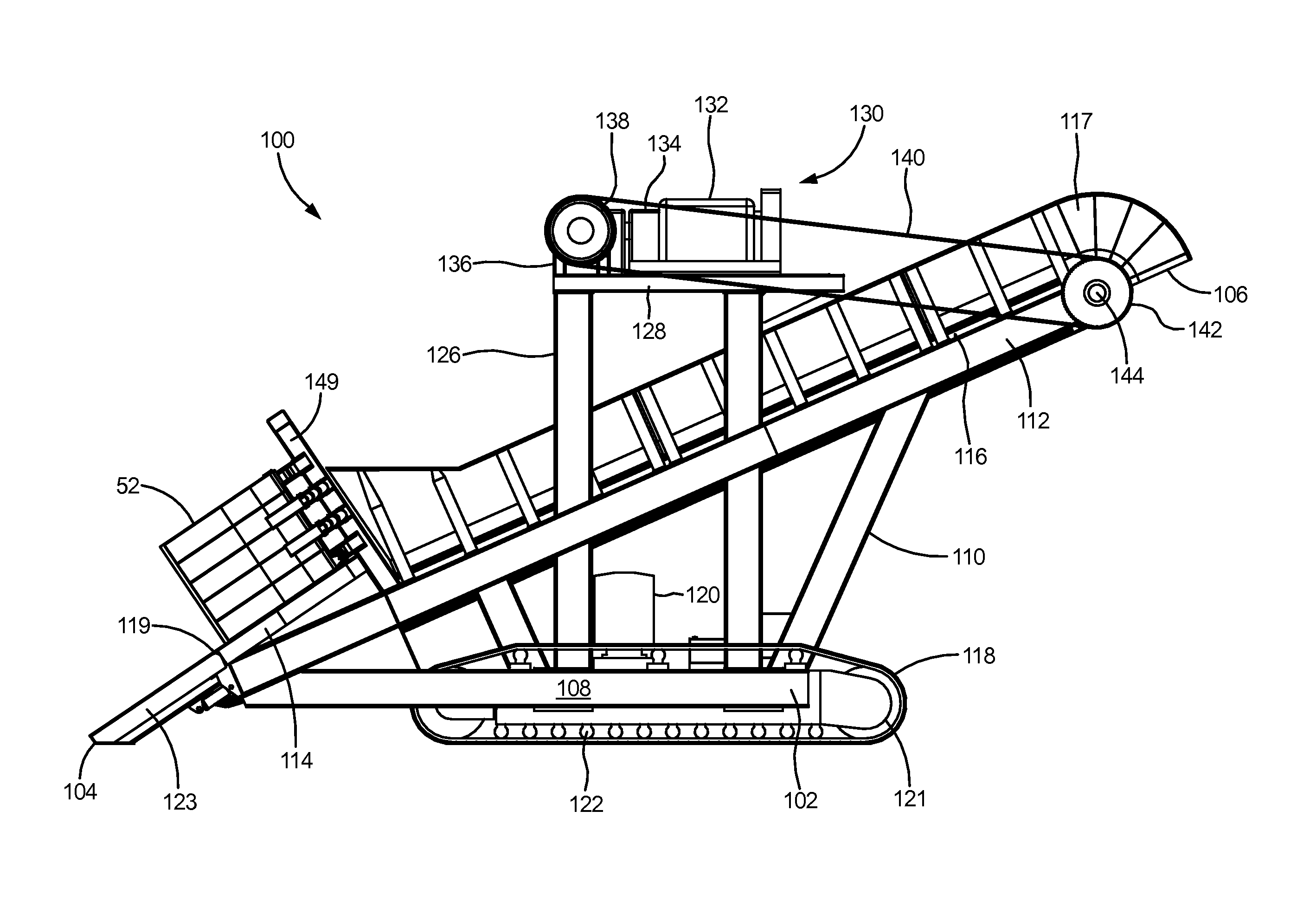
[0063]The stacker conveyor 100 in FIG. 20 includes an upper drive assembly 170. Upper drive assembly 170 uses a standard bulldozer drive train, which will include a given track gauge that is center to center of the drive sprockets on the two planetary gearboxes 136. Drive assembly 170 includes an extra drive shaft 172 mounted on the front of the drive platform 128. Drive shaft 172 will match up with the standard track gauge of the standard bulldozer drive train and also enable it to match up with the track gauge on the main head shaft 144 and to thus drive the head shaft sprockets 142 mounted outward of the conveyor sidewalls 117 and the upper frame member 112. In this embodiment of the upper drive assembly 170, a first chain 174 extends between each planetary gearbox 136 and engages inner sprockets 176 on the extra drive shaft 172. A second chain 178 engages outer sprockets 180 on the extra drive shaft 172 and engages head shaft sprockets 142 on main head shaft 144 to drive the con...


PUM


Abstract

A loading apparatus and method including a stacker conveyor having paired crawler tracks, an inclined conveyor, and an intake end and a discharge end. A wide apron is positioned at the intake end of the conveyor. The apron includes a left-hand side and right-hand side load receiving area that are arranged on opposing sides of the feeder conveyor. Two double hinged feeder blades are positioned at a rear edge of the apron. The feeder blades are arranged to operate asynchronously. Each feeder blade includes a main blade and a wing blade. A straight mechanical drive unit including an engine and two planetary gearboxes that generate the torque required to drive the conveyor. The drive unit includes a torque converter and two planetary gearboxes with planetary sprockets. A chain extends between each planetary sprocket and a corresponding head shaft sprocket on a main head shaft which drives the conveyor.

Description

[0001]This application is a Continuation-In-Part of U.S. patent application Ser. No. 13 / 770,303, which was filed on Feb. 19, 2013 and entitled “High Volume Excavating and Loading Apparatus and Method”.FIELD OF THE INVENTION[0002]This invention relates to mining machinery and more specifically to an apparatus and method for high volume excavating and loading of ores.BACKGROUND OF THE INVENTION[0003]One of the most common arrangements for moving large quantities of heavy material such as overburden from strip mining operations, earth from excavation operations, and other similar material movement, is to use large electric or hydraulic excavators to lift the material into large trucks. Hydraulic excavators come with either front shovel boom arrangements or backhoe booms.[0004]Large electric and hydraulic excavators are typically on crawler tracks and have a large volume bucket that is at the end of a boom and is commonly rated by the cubic yards of material that it will hold. The capac...

Claims


Application Information

Patent Timeline
IPC IPC(8): B65G41/00B65G47/16B65G23/24
CPCB65G41/006B65G47/16B65G23/24E02F3/32E02F7/026B65G41/008B02C1/00
Inventor LOWERY, STERLING WAYNE
Owner LOWERY STERLING WAYNE
Why Eureka
Try Eureka